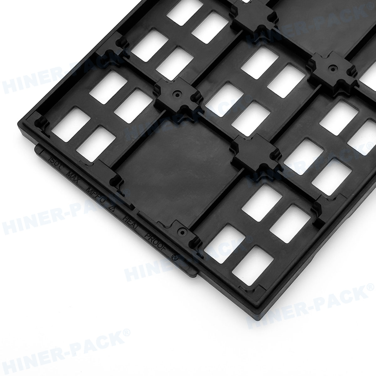
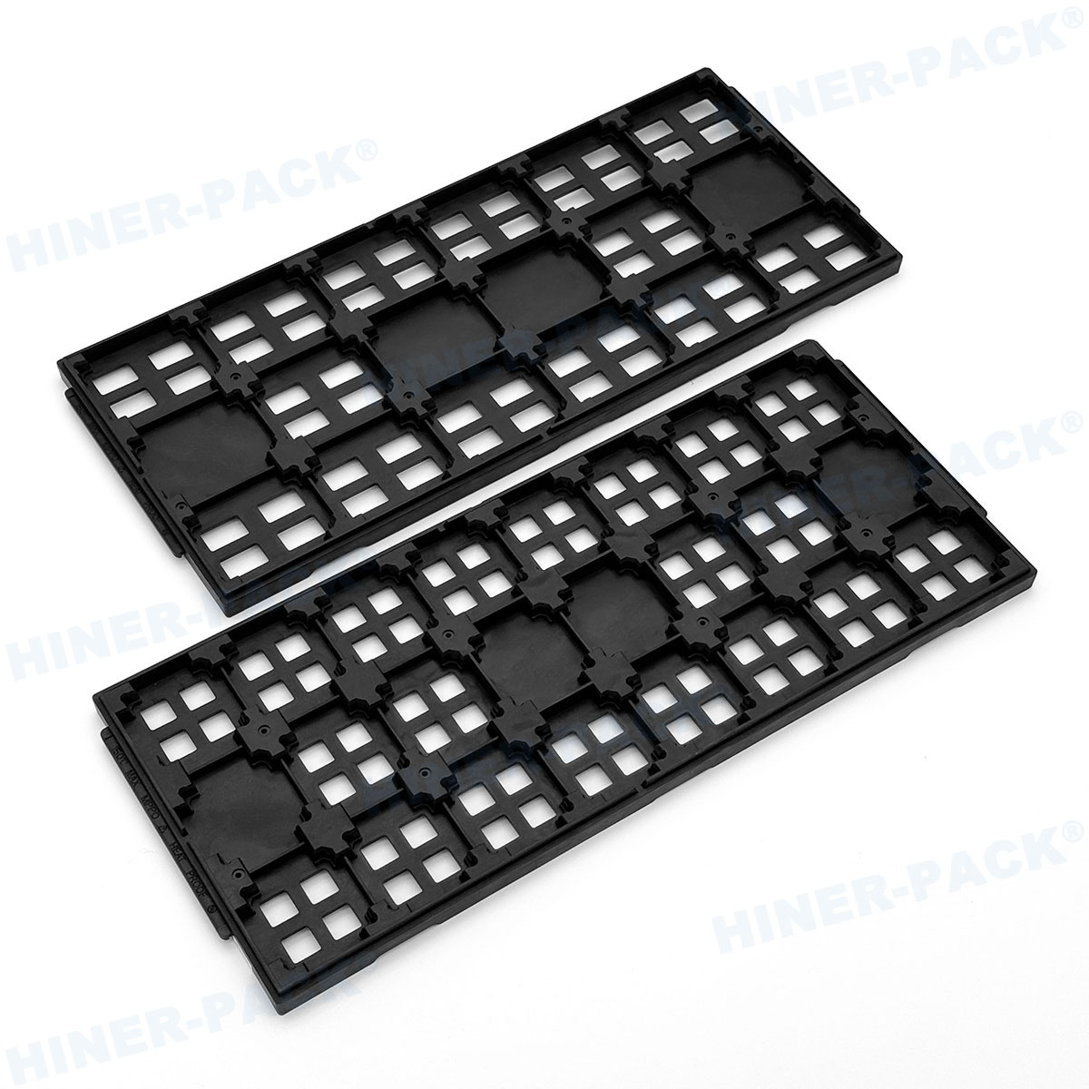
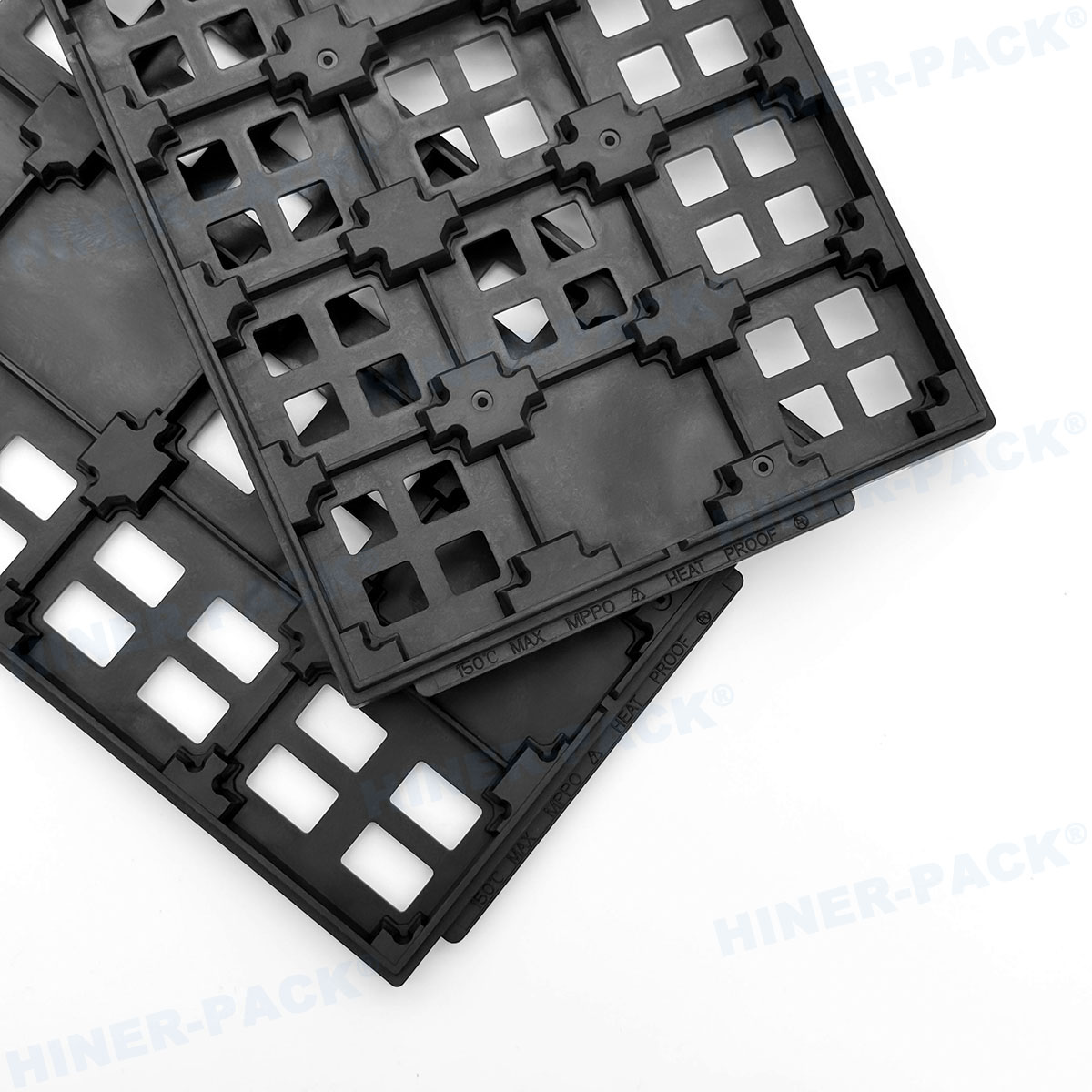
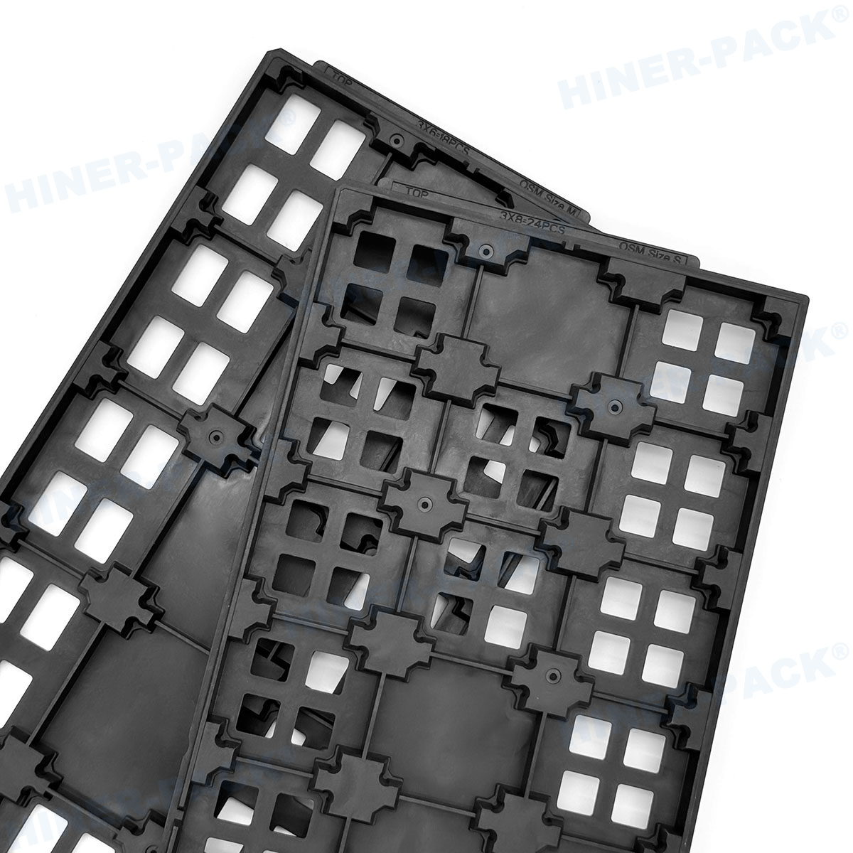
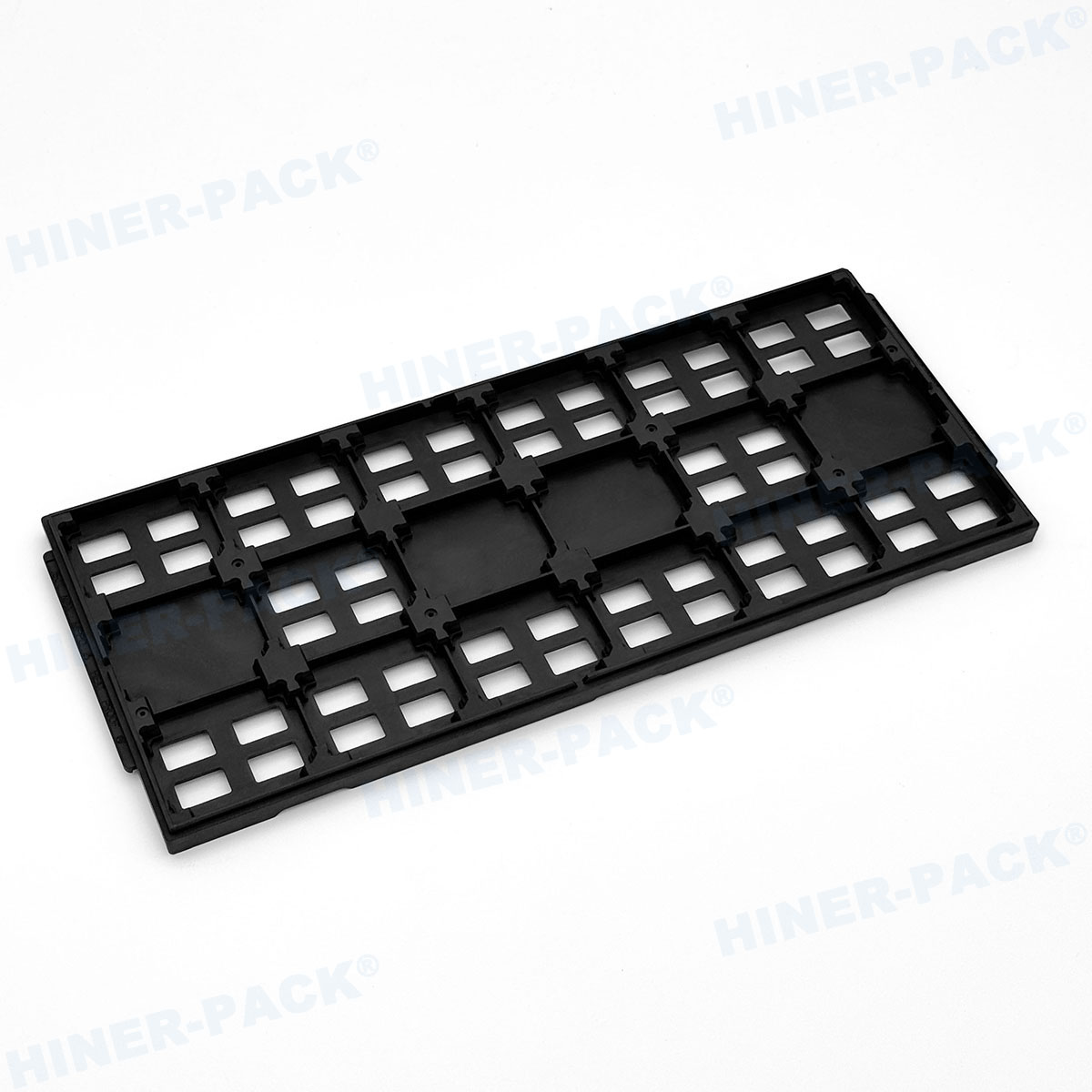
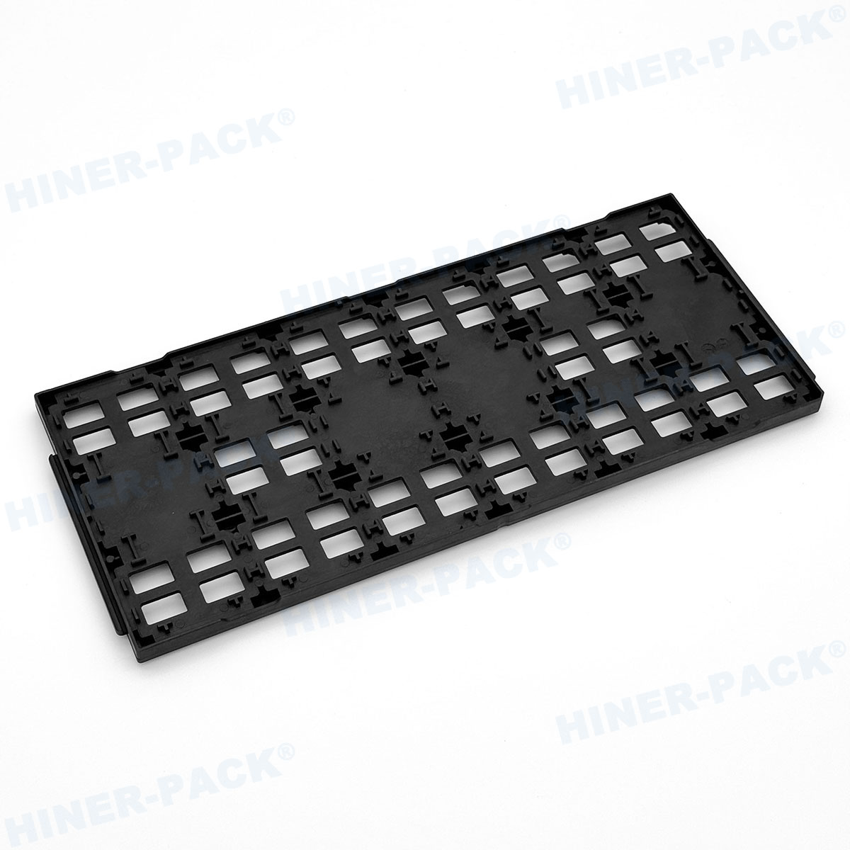
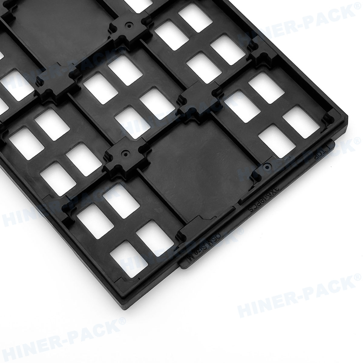
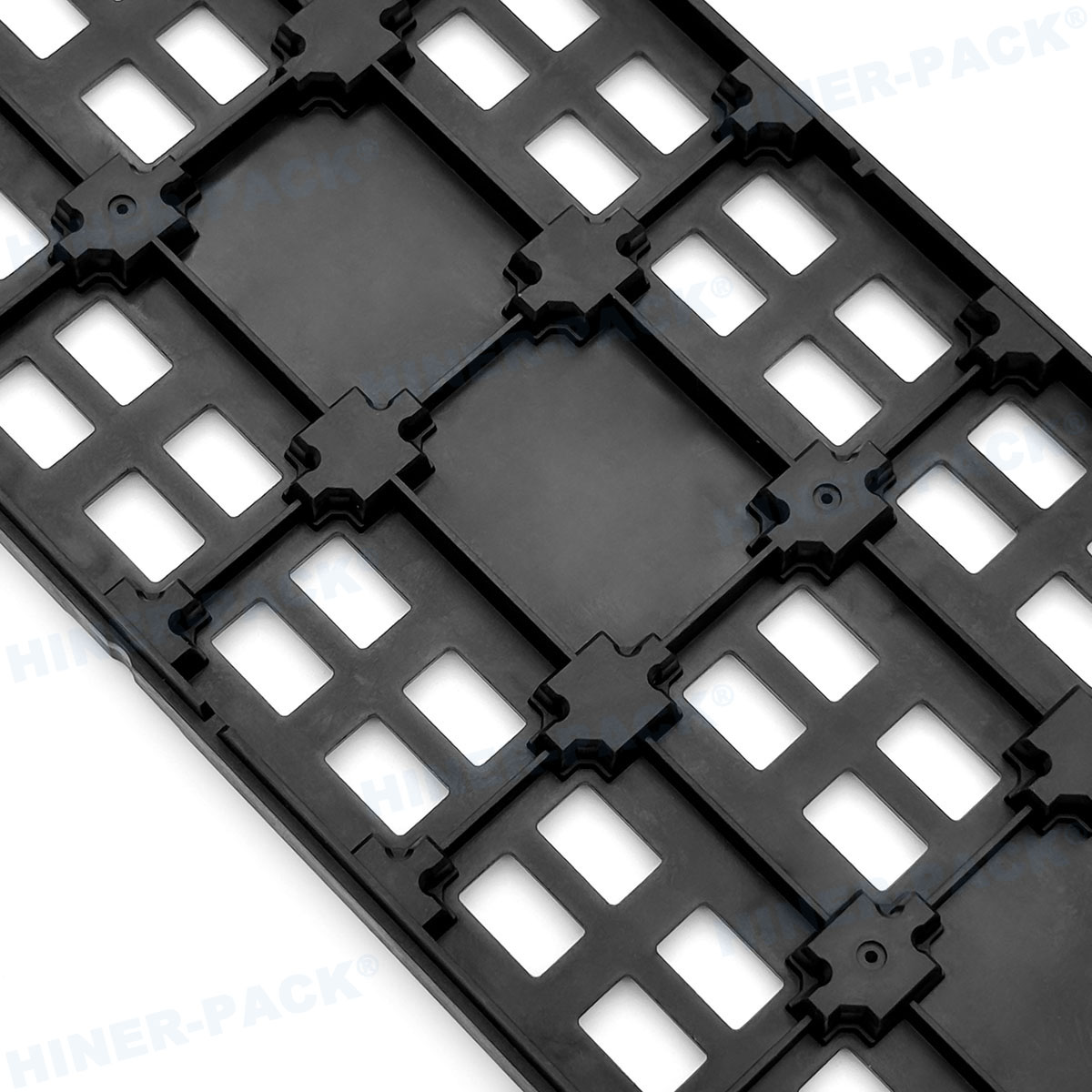
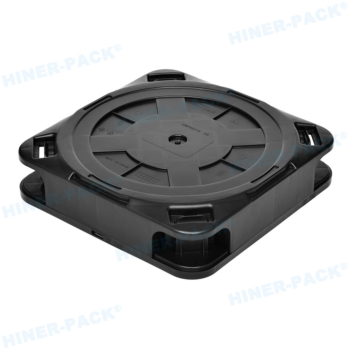
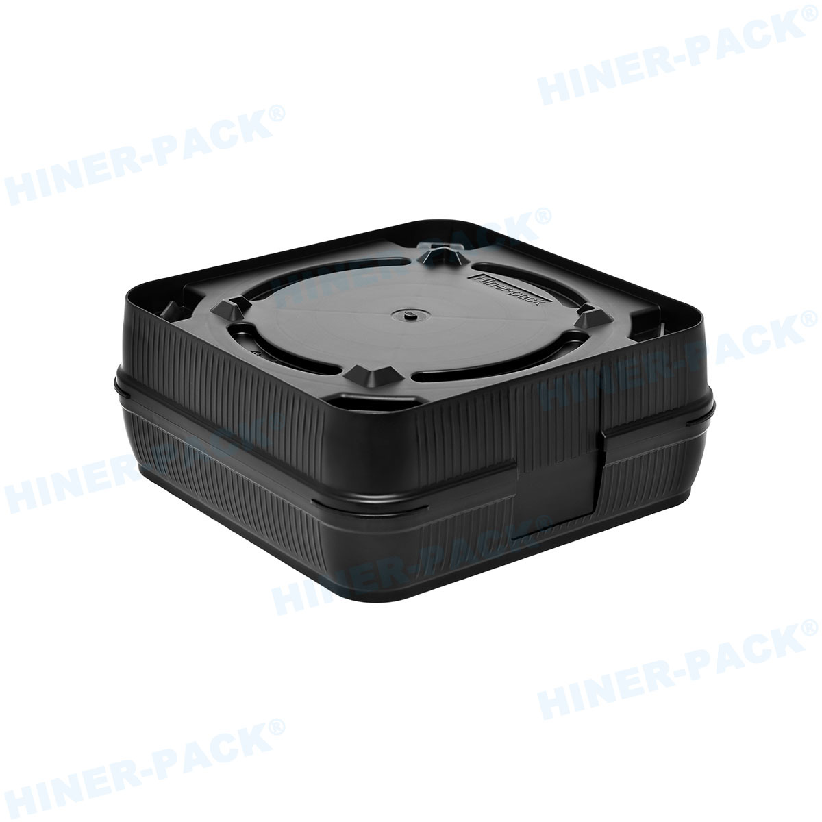
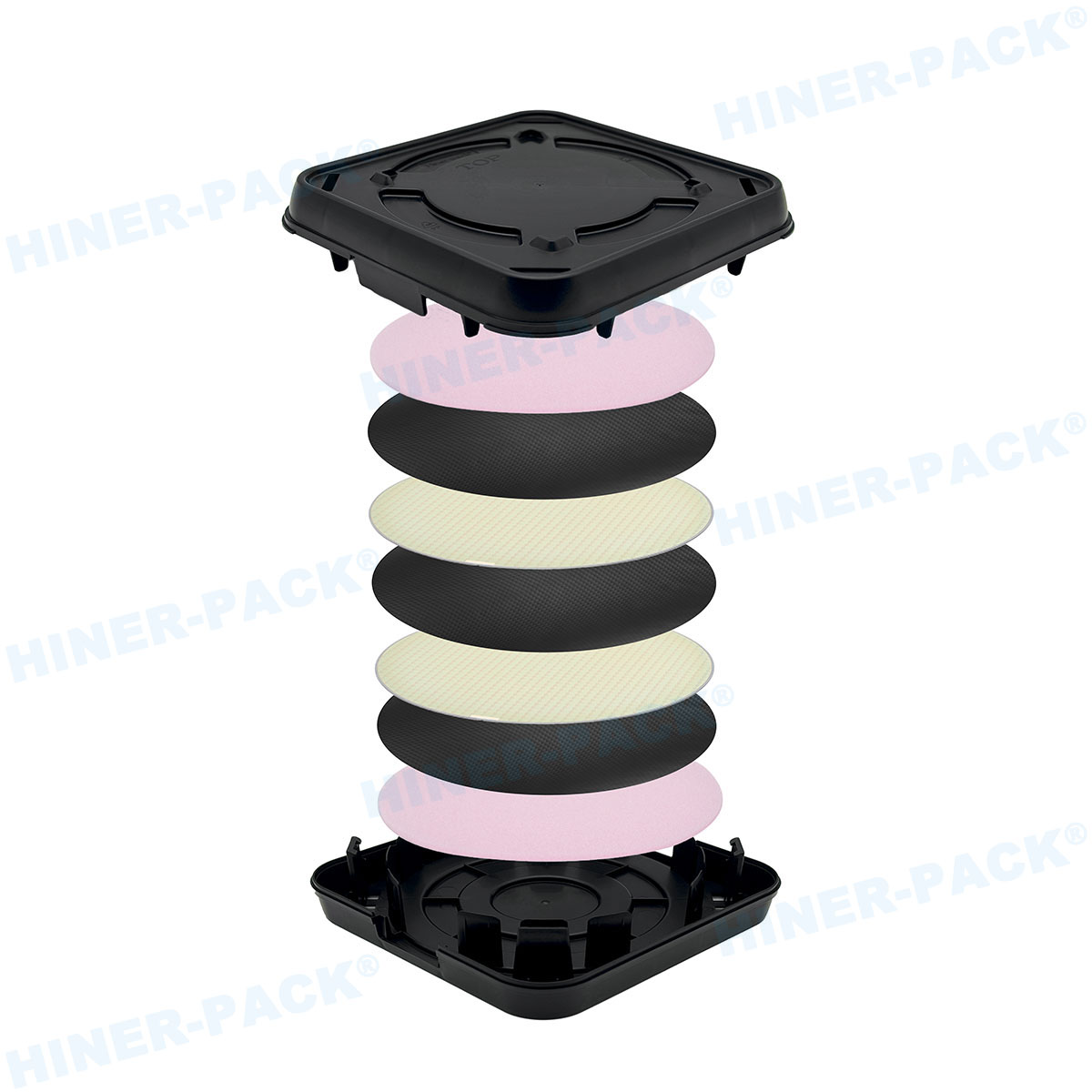
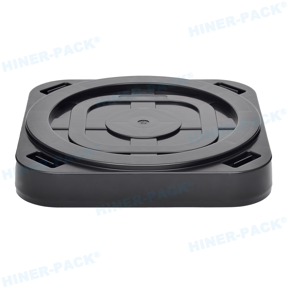
JEDEC Tray For Module Packages
- Absolutely avoid pressing or damaging pins, solder balls, or exposed connectors
- Provide stable multi-point support to the module body
- Compatibility with automated testing equipment, robotic arms, pick-and-place systems, and storage racks
- High mechanical strength
- Tray material meets ESD control requirements and withstands reflow oven, baking, or cleaning processes
- Provide stable multi-point support to the module body
- Compatibility with automated testing equipment, robotic arms, pick-and-place systems, and storage racks
- High mechanical strength
- Tray material meets ESD control requirements and withstands reflow oven, baking, or cleaning processes
×
Get a Quote
Please fill in all * fields below, we will get back to you as soon as possible.
 Video
Video
 Video
Video
 Video
Video
 Video
Video
 Video
Video
 Video
Video
 Video
Video
 Video
Video
 Video
Video
 Video
Video
 Video
Video
 Video
Video
 Video
Video