In high-volume semiconductor backend operations, the selection of material
handling interfaces directly impacts yield, equipment uptime, and component
reliability. For Ball Grid Array (BGA) packages, the standardized shipping,
baking, and surface-mount feeding processes depend on precision-molded carriers
known as BGA jedec matrix IC
trays. These trays are not passive containers; they are engineered
interfaces whose dimensional stability, electrical behavior, and thermal
resistance determine whether a batch of fine-pitch BGAs survives reflow without
coplanarity failure. This article provides a detailed technical examination of
JEDEC matrix tray standards, material selection trade-offs, industry pain
points, and validated solutions from Hiner-pack, a specialist in
precision IC handling products.
1. Defining JEDEC Matrix Trays: From Outline Drawings to Functional
Verification
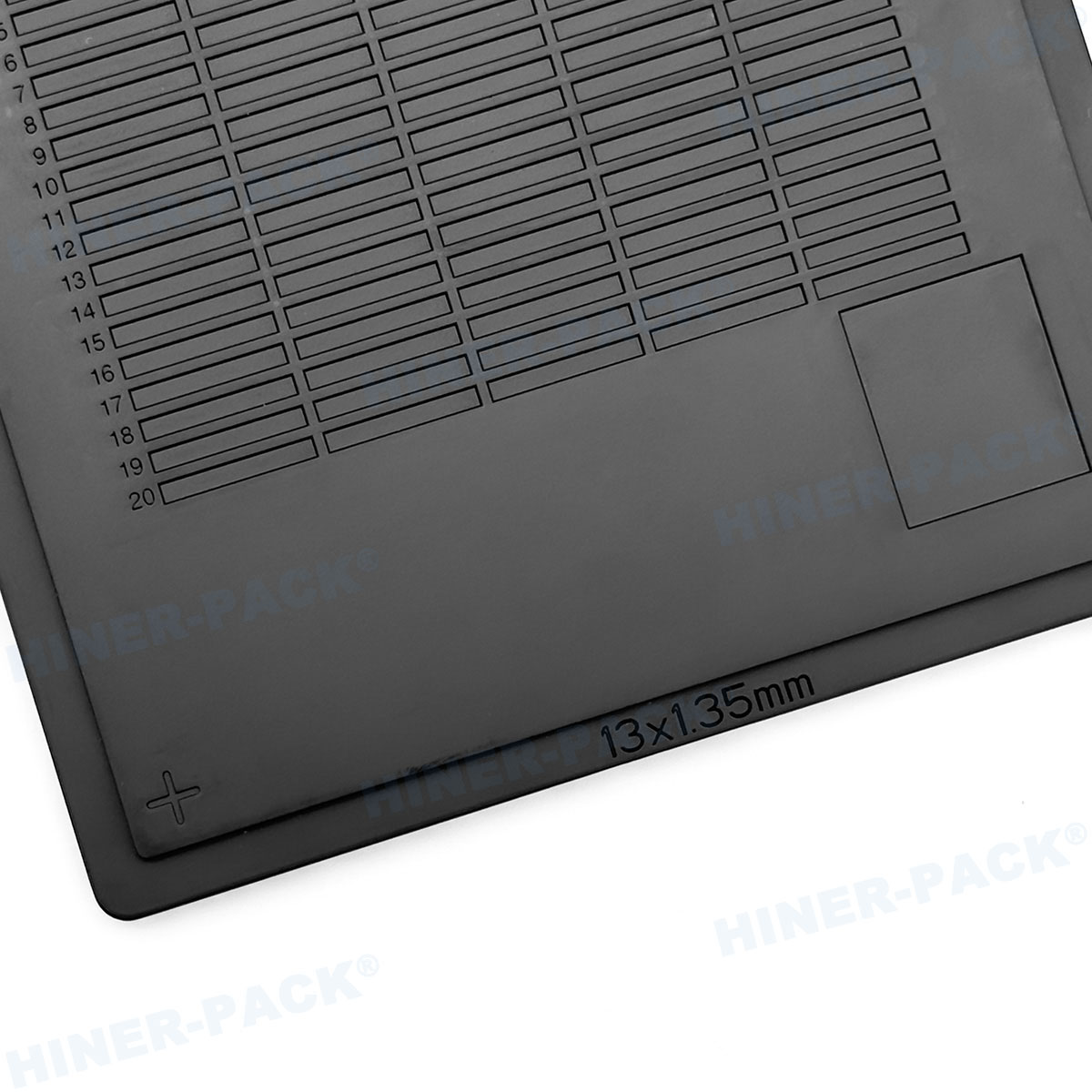
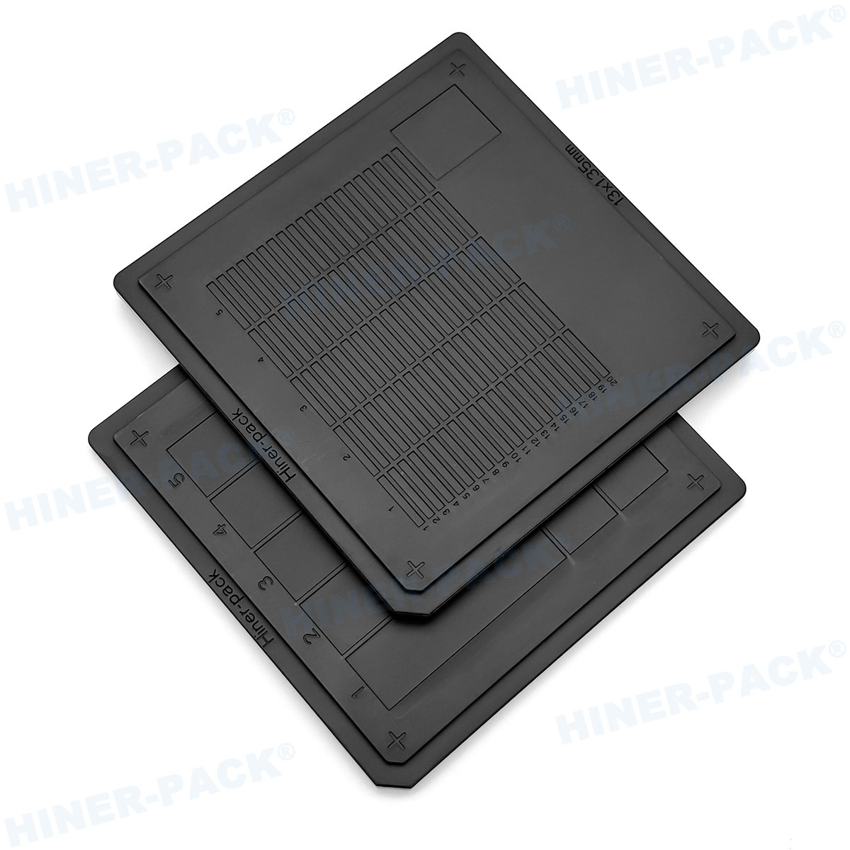
The term "matrix tray" refers to a rigid carrier with an array of cavities
(pockets) designed to hold individual BGA components during transportation,
dry-pack baking, tape-and-reel preparation, or direct placement into
pick-and-place machines. BGA jedec matrix IC
trays follow dimensional standards published by JEDEC Solid State
Technology Association, primarily under JEDEC Publication 95 (Design Standard
for Tray for Handling and Shipping of BGA and Other Surface-Mount Components).
These standards specify key parameters: tray body dimensions (e.g., 322 mm × 135
mm or 322 mm × 139 mm), pocket pitch (distance between cavity centers), pocket
depth, corner radius, and stackability features. A JEDEC-compliant matrix tray
ensures that any tray from any qualified supplier fits seamlessly into existing
dry-pack equipment, auto-tray feeders (such as those from Seiko Epson or Data
I/O), and vacuum pick-up nozzles.
Beyond mechanical dimensions, JEDEC defines classification levels for
moisture sensitivity (MSL) and recommends tray materials that withstand standard
bake temperatures of 125°C for 24 hours without excessive warpage. However, many
procurement specifications add further constraints: surface resistivity between
10⁴ and 10¹¹ Ω/sq (ESD control per ANSI/ESD S20.20), fluorine-free materials for
wafer fabs, and low particle generation (ISO Class 5 or better cleanliness).
2. Critical Technical Parameters for BGA Jedec Matrix Tray Performance
Selecting BGA jedec matrix IC
trays requires evaluating several interlinked metrics. Below are
the key parameters that separate industrial-grade trays from commodity
alternatives.
2.1 Pocket Geometry and Coplanarity Protection
Each pocket must restrain the BGA substrate without contacting or damaging
the solder balls. As BGA pitches shrink to 0.65 mm, 0.5 mm, or even 0.35 mm,
pocket dimensions must maintain a minimum clearance of 0.15 mm from the nearest
ball row. A poorly designed pocket leads to solder ball scraping, ball
deformation, or component rotation that causes feeder jams. Advanced trays
employ tapered pocket walls (2°–5° draft angles) and stepped bottom designs to
support the substrate’s edge rather than the balls.
2.2 Warpage Control Under Thermal Stress
During pre-reflow baking (typically 125°C for 24 hours, or 150°C for 4 hours
for MSL 3 components), tray warpage can exceed 0.5 mm, causing nested trays to
separate unevenly and potentially ejecting components. JEDEC limits warpage to
≤0.3 mm per 300 mm length after thermal conditioning. Material selection is
decisive: glass-filled polyetherimide (PEI) offers a heat deflection temperature
above 200°C, while conductive polycarbonate (PC) may warp above 120°C.
Hiner-pack provides trays
molded from high-flow PPS (polyphenylene sulfide) compounds that achieve warp
values below 0.15 mm after 125°C/48-hour exposure.
2.3 ESD and Surface Resistivity Consistency
Static discharge through an unprotected BGA can cause latent junction damage
or immediate failure. JEDEC trays are classified into three ESD categories:
conductive (10²–10⁵ Ω/sq), static-dissipative (10⁵–10⁹ Ω/sq), and anti-static
(10⁹–10¹¹ Ω/sq). Most leading OSATs (outsourced assembly and test providers)
specify dissipative trays because they prevent rapid discharge while avoiding
triboelectric charging. However, additives such as carbon fibers or inherently
dissipative polymers (IDPs) must be distributed uniformly; otherwise,
resistivity varies across the tray surface, creating ESD "blind spots."
High-quality trays verify resistivity with a 10V/100V electrode array per
ANSI/ESD STM11.11.
3. Application Scenarios: Where Matrix Trays Meet Process Requirements
Understanding where BGA jedec matrix IC
trays are deployed helps engineers select the correct material
grade and pocket configuration. Below are four primary use cases with distinct
demands.
Incoming IC inspection and dry-pack storage: Trays must
resist moisture absorption and survive vacuum sealing without crushing pockets.
Low-hygroscopic materials like polypropylene (PP) with anti-static coating are
common.
Pre-reflow baking (moisture removal): High-temperature
trays (PEI, PEEK, or reinforced PPS) survive 125-150°C cycles. Warpage after 24
hours must remain below 0.2 mm to avoid singulation errors.
Automated SMT assembly (direct tray feeding): Compatibility
with machine vision systems requires high-contrast tray surfaces (typically
black or matte gray) and chamfered corner pockets for component orientation
detection.
In-process transfer between rework stations: Frequent
manual handling increases risk of edge scratches and particle generation. Trays
with rounded external ribs and smooth pocket floors reduce
contamination.
Each scenario imposes trade-offs. For instance, highly conductive trays
(carbon-loaded) may shed carbon fibers, leading to particle contamination—a
critical issue in automotive BGA assembly requiring ISO Class 6 cleanrooms. Many
engineers now specify cleanroom-molded IC handling trays with low
outgassing and no silicone residues.
4. Industry Pain Points and Solutions: Moving Beyond Data Sheet
Specifications
Even when a tray meets JEDEC outline drawings, users report recurring issues
that increase defect rates. Below are four common pain points and engineering
countermeasures.
4.1 Pocket-to-Pocket Coplanarity Variation
Pain point: After several reflow cycles, some pockets warp
differently due to non-uniform wall thickness, causing BGAs to sit tilted.
Pick-up failures rise from 50 ppm to over 500 ppm.
Solution: Mold flow simulation during tool design ensures uniform cavity filling and
cooling. Hiner-pack employs dynamic
temperature control in injection molds, achieving pocket coplanarity within
±0.03 mm across all 336 pockets of a 12×28 matrix.
4.2 Tray stacking instability and component ejection
Pain point: Stacking interlock features (posts and sockets)
wear after 50 cleaning cycles, leading to tray tilt and BGA spillage during
conveyor transfer.
Solution: Using wear-resistant alloys in
stacking features or designing replaceable interlock inserts extends stack life
to >500 cycles. Also, tapered alignment edges guide trays automatically.
4.3 Particle contamination from tray abrasion
Pain point: BGAs slide against pocket walls during shipping,
generating sub-50 µm particles that migrate to solder balls, causing
head-in-pillow defects.
Solution: Molded-in lubricants
(e.g., PTFE-modified polymers) reduce coefficient of friction from 0.4 down to
0.15. Additionally, pocket floors with micro-dot texture raise the BGA substrate
slightly, minimizing contact area.
4.4 Mismatch with legacy auto-tray feeders
Pain point: New tray batches have slightly different edge
radii or stacking heights, causing feeder clutch
misfeeds.
Solution: Reverse engineering of original tray
geometry using 3D scanning and adjusting mold parameters to match existing
feeders. Many custom matrix trays from
specialized manufacturers offer ±0.1 mm tolerance on critical
datums.
5. Material Engineering: Conductive, Dissipative, and Antistatic Trays
Compared
Material choice affects cost, durability, ESD performance, and temperature
range. The following table summarizes key differences (as textual
comparison):
Polypropylene with antistatic coating: Low cost, good for
dry storage at room temperature, but coating wears off after 30-50 washes.
Coating resistivity drifts from 10⁹ to 10¹² Ω/sq over time.
Carbon-filled polycarbonate (PC): Dissipative (10⁶–10⁹
Ω/sq), temp resistance up to 110°C, but prone to warpage above 125°C. Suitable
for automated assembly lines with ambient conditions.
Polyetherimide (PEI) with inherent dissipation: Stable up
to 170°C, very low warpage, dissipative without fillers. Expensive, used for
high-reliability BGA (automotive, medical).
Polyphenylene sulfide (PPS) with carbon fiber: Conductive
range (10²–10⁵ Ω/sq), excellent chemical resistance, withstands 200°C
short-term. Preferred for burn-in board trays. The main drawback is brittleness
and high tooling wear.
A growing trend is the use of inherently dissipative polymer (IDP) blends,
which do not rely on migratory antistatic agents and maintain resistivity across
humidity changes. For most BGA applications with 0.8 mm pitch and above,
carbon-loaded PC or PPS provides the best price-to-performance ratio.
6. Cleaning, Storage, and Lifecycle Management of JEDEC Matrix Trays
Maximizing tray reuse lowers packaging costs but introduces contamination
risks. Standard industry practice includes:
Washing: Ultrasonic cleaning in deionized water with
non-ionic detergents, followed by hot air drying at 60-70°C. Harsh solvents
(acetone, IPA >70%) can extract antistatic agents.
ESD requalification: After 20 washes, measure surface
resistivity again. If it exceeds 10¹¹ Ω (or specified limit), the batch should
be downgraded to non-ESD sensitive components.
Warpage inspection: Using a granite plate and feeler gauge,
check that tray flatness remains within 0.3 mm across diagonal corners. Replace
trays exceeding limit.
Typical lifespan: A well-maintained tray made of filled PC
or PEI lasts 200-300 wash cycles; carbon-PPS trays can exceed 500 cycles if
handled gently. Hiner-pack offers tray
recertification services where we measure and re-certify ESD/flatness parameters
for a fraction of new tray cost.
7. Future Directions: High-Density and Ultra-Fine-Pitch BGA Trays
As 2.5D and 3D IC packages become more common, BGA ball pitches drop to 0.35
mm and even 0.3 mm. This creates two major challenges for matrix tray
design:
Pocket wall thickness: With pitch below 0.5 mm, the wall
between adjacent pockets may be less than 0.25 mm, risking breakage during
molding. Advanced tooling with high-speed micro-milling and lubricated core pins
solves this.
Solder ball contact avoidance: At 0.35 mm pitch, ball
diameter is usually ~0.2 mm. Any pocket misalignment >0.05 mm can scrape
balls. This demands mold alignment precision of ±0.01 mm, which is achievable
with CNC-machined electrode manufacturing.
Additionally, embedded RFID tags in trays are being deployed by leading OSATs
to track cycle count, bake history, and ownership. This smart tray concept,
integrated with factory execution systems, reduces misplacement and improves
traceability.
Frequently Asked Questions (FAQ)
Q1: What are the standard dimensions of a JEDEC matrix tray for BGA
packages?
A1: The most common JEDEC tray outline is "Tray Type 1" with
dimensions 322 mm × 135 mm (12.68" × 5.31"). Other variants include 322 mm × 139
mm and 322 mm × 148 mm, depending on pocket array (e.g., 12×21, 16×24). Always
refer to JEDEC MO-xxx design files for exact pocket pitch and cavity depth,
which vary by BGA body size and ball diameter.
Q2: Can I bake BGA components at 125°C directly inside the tray?
A2: Yes, but only if the tray material is rated for that
temperature. Standard polycarbonate trays may warp permanently above 110°C. Use
trays molded from PEI, PPS, or high-temperature PC compounds, and verify the
manufacturer's continuous use temperature. Many bakeable IC trays from
Hiner-pack specify 150°C/48h without loss of flatness.
Q3: How do I clean JEDEC trays without removing ESD properties?
A3: Clean using mild alkaline detergents (pH 7-9) or
deionized water with ultrasonication, followed by forced air drying at 50-60°C.
Avoid abrasive brushes, high-pressure jets, or solvents like toluene and MEK.
After cleaning, perform a resistivity test per ANSI/ESD STM11.13; if values
exceed 10¹¹ Ω/sq, apply topical antistatic spray or retire the tray.
Q4: What is the difference between "matrix tray" and "JEDEC tray"?
A4: "Matrix tray" describes any molded tray with an array of
pockets. "JEDEC tray" specifically refers to a matrix tray that complies with
the dimensional, material, and marking standards published by JEDEC. Therefore,
all BGA jedec matrix IC
trays are matrix trays, but not all matrix trays are
JEDEC-compliant. Non-JEDEC trays may cause feeder compatibility issues.
Q5: How many times can a single tray be reused before it should be
scrapped?
A5: Lifespan depends on material and process conditions. For
carbon-filled PC trays in ambient temperatures (no baking), 150-200 cycles are
typical. For high-temperature PEI trays undergoing frequent baking, 300-400
cycles. Scrapping criteria: warpage >0.4 mm, cracked pocket walls, or surface
resistivity >10¹¹ Ω/sq. Many facilities requalify every 50 cycles using a
sample inspection plan.
Selecting the Right BGA JEDEC Matrix Tray Partner
Engineers responsible for BGA handling should move beyond simple dimension
checks and evaluate material behavior under actual process conditions—thermal
aging, cleaning chemistry compatibility, and ESD stability after wear. The shift
to finer-pitch BGAs and higher-temperature lead-free reflow processes demands
trays that maintain sub-0.2 mm coplanarity and consistent resistivity through
hundreds of cycles. Hiner-pack provides fully
JEDEC-compliant BGA jedec matrix IC
trays machined from wear-resistant, high-temperature polymers, with
metrology reports for every batch. Our engineering team assists with pocket
geometry optimization for non-standard BGA substrates and rapid tooling
modifications.
For detailed technical datasheets, sample trays, or a consultation on
reducing your BGA handling defects, please send your specification to our
technical sales team. Request your quote or free contamination audit
today – Hiner-pack ensures your ICs arrive at the placement machine in perfect
condition.
Contact Hiner-pack for
BGA JEDEC matrix tray inquiries: provide your BGA dimensions, MSL level, and
automation feeder model – we will propose the optimized tray material and pocket
design within 48 hours.