In semiconductor back-end operations, the JEDEC
tray cover is a precision component that directly affects die
protection during inter-facility transport, automated depalletizing, and
long-term storage. JEDEC outlines (e.g., 322x226mm, 336x230mm) define tray
pocket arrays, but the cover — often overlooked — must satisfy identical
flatness, resistivity, and cleanliness criteria. Without a correctly specified
cover, OSATs and IDMs face yield losses from ESD damage, particle contamination,
and misaligned stacking in pick-and-place equipment. This guide provides
semiconductor quality engineers and procurement specialists with actionable data
on JEDEC tray cover material science, failure modes, and
reusability protocols. Hiner-pack offers JEDEC-compatible tooling with full
metrology traceability.
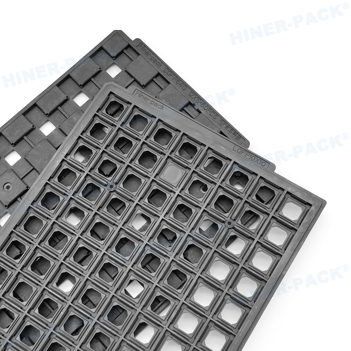
1. JEDEC Dimension Compliance and Mechanical Fit
A JEDEC tray cover must match the tray’s peripheral locking
features, alignment ribs, and overall outline. Two common JEDEC formats are
MS‑009 (322 mm x 226 mm) and MS‑012 (336 mm x 230 mm), but many custom variants
exist. Critical dimensions include:
Overall width and length: Tolerance ±0.10 mm to avoid
overhang or underhang that causes handling errors.
Corner radius and latch geometry: Mismatched latch angles
(standard 2°–5° draft) lead to cover popping off during vibration.
Overall height (cover thickness): Typically 2.8–3.5 mm. Too
thin leads to warpage; too thick blocks automated tray stackers.
Using non‑compliant lids forces manual rework. One ASEAN OSAT reported a 12%
increase in equipment jams after switching to an unbranded cover with
out‑of‑spec locating pins. A proper JEDEC
tray cover undergoes 100% optical measurement for these features.
Hiner-pack supplies covers with a CMM report per batch,
including datums A, B, and C per ASME Y14.5.
2. Material Science: Conductive vs. Dissipative vs. Antistatic Grades
Selecting the right polymer for a JEDEC tray cover requires
balancing surface resistivity, mechanical rigidity, and ionic contamination
limits. Below are three industry-proven options and their suitability:
Conductive Polycarbonate (carbon fiber or carbon nanotube
loaded): Resistivity 10³–10⁵ Ω/sq, fast charge decay. Preferred for
high-speed automation where tribocharge from cover removal must stay below 100V.
Slightly higher cost and potential carbon shedding.
Dissipative ABS/PC blend (permanent antistatic agent): Resistivity 10⁶–10⁹ Ω/sq. Offers good impact strength and lower particle
generation. Suitable for cleanroom class 10,000 applications.
Antistatic PET or PET-G (topical or migrated agent): Resistivity 10⁹–10¹¹ Ω/sq. Low cost but prone to agent migration after multiple
washes; flatness degrades above 70°C.
For advanced nodes (<28nm), choose a JEDEC tray cover that passes outgassing tests per SEMI F57 (no siloxanes, amides, or plasticizers
above 0.1 µg/g). Hiner-pack uses mineral‑filled PC with
inherent dissipation, eliminating carbon black shedding while maintaining
10⁸–10¹⁰ Ω/sq even after 20 cleanings.
3. Key Performance Metrics for Supplier Validation
Engineers should request five quantifiable test results for each
JEDEC tray cover batch:
Flatness (warpage) measured on a granite surface plate: Maximum deviation ≤0.20 mm over 300 mm length. Higher warpage creates vacuum
leak during die pickup.
Surface resistivity per ANSI/ESD STM11.11: At least five
points, recorded after 50% RH conditioning. Acceptable range depends on ESD
control plan (typically 10⁵–10¹¹ Ω/sq).
Tribocharge generation (cover separation from tray): Measured with Faraday cup and electrometer. Peak voltage should not exceed 200V
for Class 0 devices.
Retention force of locking clips: Average 20–35 N per
latch, with less than 15% variation across all latches.
Liquid particle count (LPC) per IEST-RP-CC004.3: ≤200
particles >0.5 µm per 100 cm² after standard cleaning.
Suppliers that cannot provide raw data for these metrics typically lack
process control. One automotive Tier‑1 replaced their incumbent after
discovering 38% of delivered covers failed flatness >0.35 mm, leading to wire
sweep incidents.
4. Failure Mechanisms and Engineered Solutions
Field data from three European assembly subcontractors isolates four common
failures tied to poor JEDEC tray cover design or material
instability:
Failure: Cover warpage after 85°C/85% RH storage (JEDEC
JESD22‑A101). Leads to tray stack tilting and ICs falling out of
pockets.
Solution: Use annealed polycarbonate with 20% glass
fiber. Preheat covers at 100°C for 2h before first use to relieve residual
stress.
Failure: Surface resistivity drift above 10¹² Ω/sq after
isopropyl alcohol (IPA) wiping. Causes electrostatic attraction of airborne
particles.
Solution: Specify inherently dissipative polymer
(IDP) rather than topical antistatic coatings. IDP maintains resistivity after
100 IPA wipes.
Failure: Locking clip breakage after 10 automation cycles.
Fracture surfaces show brittle failure due to sharp corner
radii.
Solution: Redesign latch with radius ≥0.4 mm and
conduct FEA stress analysis. Hiner-pack applies a 0.5 mm radius
and uses PC+ABS blend to improve ductility.
Failure: Cover stick‑slip vibration during high-speed tray
separation, generating false sensor triggers in test
handlers.
Solution: Add micro‑textured contact ribs (0.1 mm
height, 2 mm pitch) on the cover inner surface. This reduces friction
coefficient from 0.55 to 0.32.
5. Cleanroom Integration and Reusability Protocol
For high‑mix fabs, reusing JEDEC tray covers reduces
packaging costs by 30–45%, but only when a validated cleaning process exists.
Recommended workflow:
Incoming inspection: Reject any cover with visible flash,
sink marks, or surface scratches >0.2 mm width.
Washing parameters: Ultrasonic bath (40 kHz, 50°C) using 2%
alkaline detergent (pH 11) for 10 min, followed by three DI water rinses (18
MΩ·cm). Drying in HEPA‑filtered oven at 55°C for 1.5h.
Re‑qualification after each 10 cycles: Measure flatness,
resistivity, and inspect latches with 10× magnification. Discard if warpage
exceeds 0.25 mm or any latch crack detected.
Using a validated cleaning protocol, a well‑designed JEDEC
tray cover can survive 25 cycles without performance degradation.
Hiner-pack provides a wash‑validation service to certify cover
lifetime under customer‑specific detergents.
6. Automated Handling Compatibility – Pick & Place and Tray
Stackers
Modern surface mount lines use tray stackers that automatically feed
magazines or destack individual trays with covers. For error‑free operation, the
JEDEC tray cover must satisfy:
Robotic grip features: Uniform side-wall texture (Ra
1.2–1.5 µm) for vacuum gripper adherence.
Cover deflection under stack pressure: At 10 trays stacked
(total ~5 kg load), deflection should stay below 0.3 mm to maintain device
clearance.
Magnetic or metal‑free compatibility: Some high‑frequency
test environments require non‑magnetic covers. Use stainless steel‑free polymer
or full plastic.
Three major pick‑and‑place OEMs (Fuji, Siemens, Hanwha) publish tray stacker
clearance specifications: cover height variation ±0.15 mm maximum. A warped or
over‑thick cover causes misfeeds and machine alarms, reducing throughput by
15–20%.
7. Supplier Auditing: Seven Critical Questions
Before qualifying a vendor for JEDEC tray cover supply,
procurement teams should request evidence on:
In‑house mold flow simulation to predict weld‑line locations and sink marks
on latching areas.
ESD testing under actual factory conditions (not just lab at 23°C). Demand
tribocharge data at 10% RH and 50% RH.
Statistical process control (SPC) charts for flatness — Cpk ≥1.33 indicates
stable molding.
Outgassing reports according to SEMI F57 or equivalent for cleanroom
consumables.
Metal particle detection (ICP‑MS analysis of wash extract) for covers used
in sensitive MEMS fabs.
Documented repeatability of cleaning cycles (same LPC results after 5, 10,
15 washes).
Fast changeover capability for custom JEDEC formats — lead time for new
cover mold.
Hiner-pack maintains open access to all manufacturing
records and offers a 48h sample service for standard JEDEC outlines.
8. Conclusion: From Generic Lid to Engineered Cover
Moving from a generic film or poorly molded lid to a qualified JEDEC
tray cover yields measurable improvements: reduced ESD field
failures (up to 60% drop), lower particle contamination (improved bond pad
yield), and fewer machine jams. The initial cost of a high‑grade cover is offset
by reusability and defect reduction. For OSATs and IDMs, specifying flatness,
resistivity range, and latch retention force in procurement contracts is now
industry best practice. Suppliers like Hiner-pack provide
full documentation, ensuring compliance with automotive IATF 16949 and SEMI
standards.
Frequently Asked Questions (FAQ) About JEDEC Tray Cover
Q1: What exactly makes a tray cover “JEDEC
compliant”?
A1: A JEDEC-compliant tray cover matches the outer form
factor, mounting hole pattern, and latch positions defined in a JEDEC
publication (e.g., MS‑009, MS‑012). It must also pass dimensional checks per
JEDEC JEP95 for tray-related features. However, JEDEC does not dictate material
or ESD properties — those are customer specifications.
Q2: Can I use the same JEDEC tray cover for both shipping and in‑fab
storage?
A2: Yes, but check two factors: cover thickness must allow
automated stacker clearance, and material must withstand repeated deionized
water cleaning. Many shipping‑only covers use low‑cost PET that warps after one
wash. For dual use, specify polycarbonate or ABS/PC with ≤0.15% moisture
absorption.
Q3: How do I measure cover warpage without expensive
equipment?
A3: Place the cover on a certified granite surface plate
(grade AA) and use a dial indicator mounted on a stand. Measure deflection at
nine grid points (center, four edges, four corners). Acceptable max difference:
0.20 mm over the longest dimension. For quick checks, a feeler gauge under a
straight edge can indicate severe warpage >0.3 mm.
Q4: What surface resistivity range is recommended for covers used
with highly sensitive CMOS devices (≤14nm)?
A4: For devices with
gate oxide breakdown voltage below 10V, use a cover with surface resistivity
between 10⁵ Ω/sq and 10⁸ Ω/sq, and ensure charge decay time <0.2 seconds from
1000V to 100V. Higher resistivity (10⁹–10¹¹ Ω/sq) may still generate damaging
triboelectric charges during rapid cover removal. Consult ANSI/ESD SP10.1 for
handling extremely ESD‑sensitive components.
Q5: Can Hiner-pack produce a JEDEC tray cover with custom color
coding for different product families?
A5: Yes. Hiner-pack offers
color additives (blue, green, yellow, black) that do not alter surface
resistivity or outgassing profile. Minimum order quantity for custom color is
2,000 pieces. Color coding helps visual lot segregation and reduces mix‑ups
during manual rework.
Need a validated JEDEC tray cover for your specific package type and
automation line? Provide your tray drawing (or JEDEC outline number)
and ESD control plan. Hiner-pack delivers sample covers with
flatness maps and tribocharge test results. For production orders, we supply
fully traceable batches with CMM and LPC reports.
Request a quote or free evaluation sample → Visit our
product page or contact our semiconductor packaging team. Click here for
inquiry and mention “JEDEC tray cover guide” for priority
engineering support.