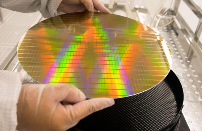
In semiconductor manufacturing and packaging, protecting integrated circuits (ICs) during handling, transport, and storage is critical. JEDEC trays are the industry-standard solution for this purpose. Among these, stackable JEDEC tray options offer significant advantages in space efficiency and logistics. This article provides a detailed look at the types, features, and selection criteria for these essential components.
Understanding JEDEC Trays and the Need for Stackability
JEDEC trays are molded carriers designed to hold ICs securely. They conform to standards set by JEDEC (Joint Electron Device Engineering Council), ensuring compatibility with automated handling equipment across the global supply chain.
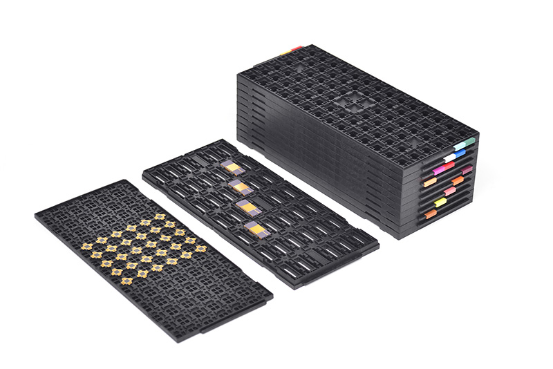
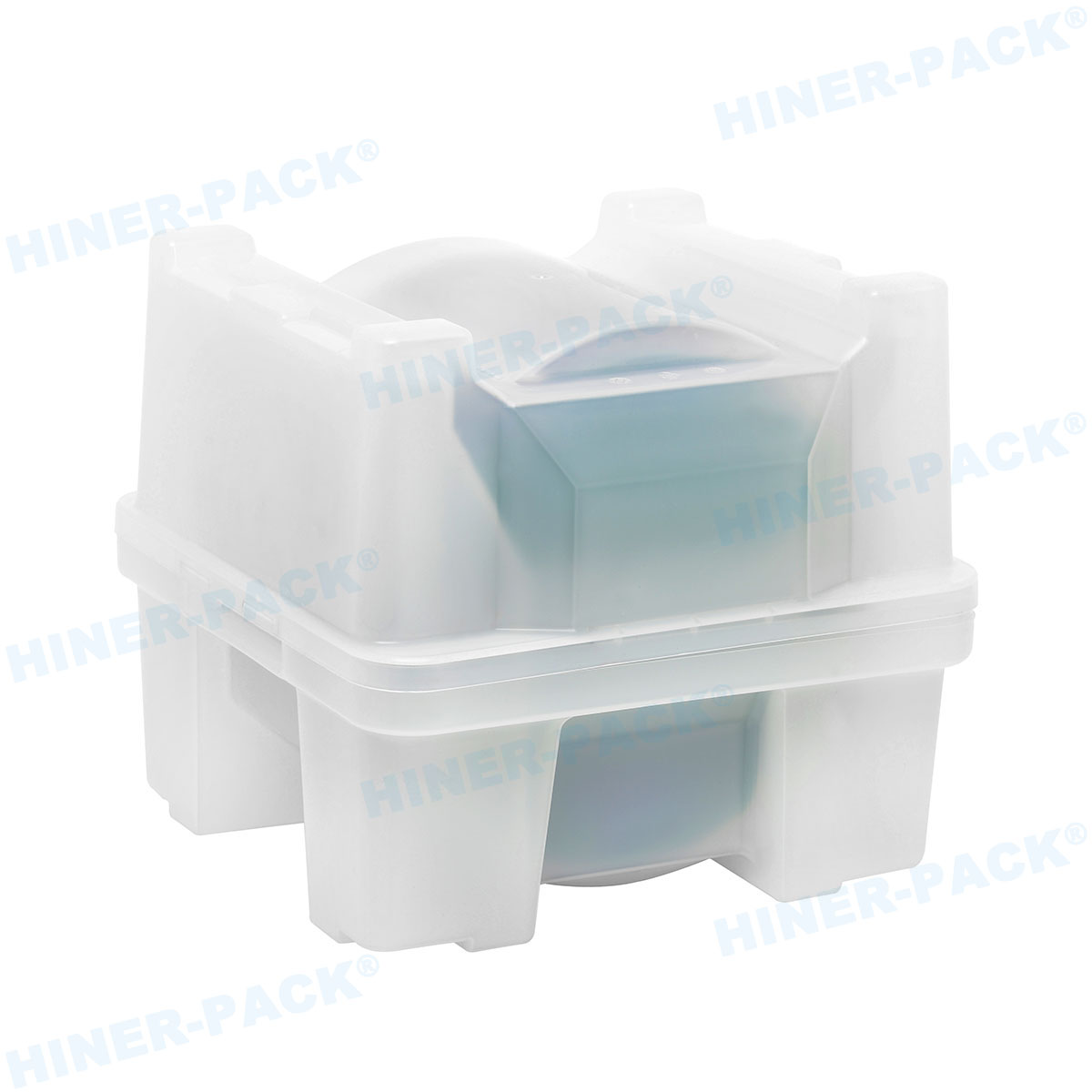
Stackability is a key feature that enhances their utility. It allows multiple loaded trays to be safely stacked, maximizing vertical space in storage, shipping containers, and on production floors.
Benefits of Using Stackable Trays
Space Optimization: Dramatically reduces the footprint needed for storing or shipping large quantities of ICs.
Improved Handling Efficiency: Enables bulk movement of units without individual handling, reducing labor and time.
Enhanced Protection: Properly designed stackable trays prevent crushing and minimize lateral movement of components.
Process Standardization: Facilitates smooth workflow between assembly, test, and shipping areas.
Key Material Choices for Stackable JEDEC Trays
The material of a tray directly impacts its performance, durability, and suitability for specific environments. When evaluating stackable JEDEC tray options, material is a primary consideration.
Antistatic Dissipative Plastics
This is the most common and critical material type for handling modern ICs.
Purpose: Safely drains electrostatic charge to prevent Electrostatic Discharge (ESD) damage to sensitive components.
Materials: Often made from carbon-loaded or permanently static-dissipative polycarbonate (PC) or polyethylene terephthalate (PET).
Use Case: Standard for all active ICs, from assembly to final packaging.
Conductive Plastics
These provide a higher level of ESD protection by offering very low electrical resistance.
Purpose: Creates a Faraday cage effect, shielding components from external static fields.
Materials: Typically use higher loadings of carbon or metal fibers.
Use Case: Essential for ultra-sensitive devices, such as certain RF or high-precision analog components.
High-Temperature Resistant Materials
Some processes require trays that can withstand elevated temperatures.
Purpose: To endure baking processes or lead-free solder reflow profiles without warping.
Materials: High-temperature variants of PC, Polyetherimide (PEI), or Polyphenylene Sulfide (PPS).
Use Case: IC baking, burn-in testing, and surface-mount technology (SMT) processes.
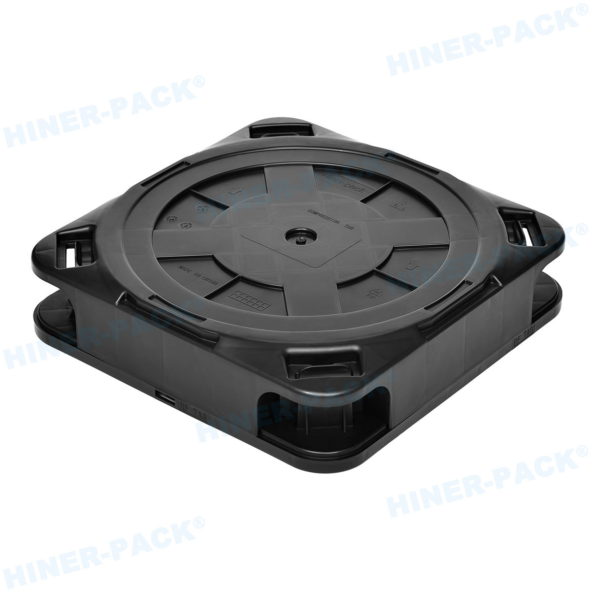
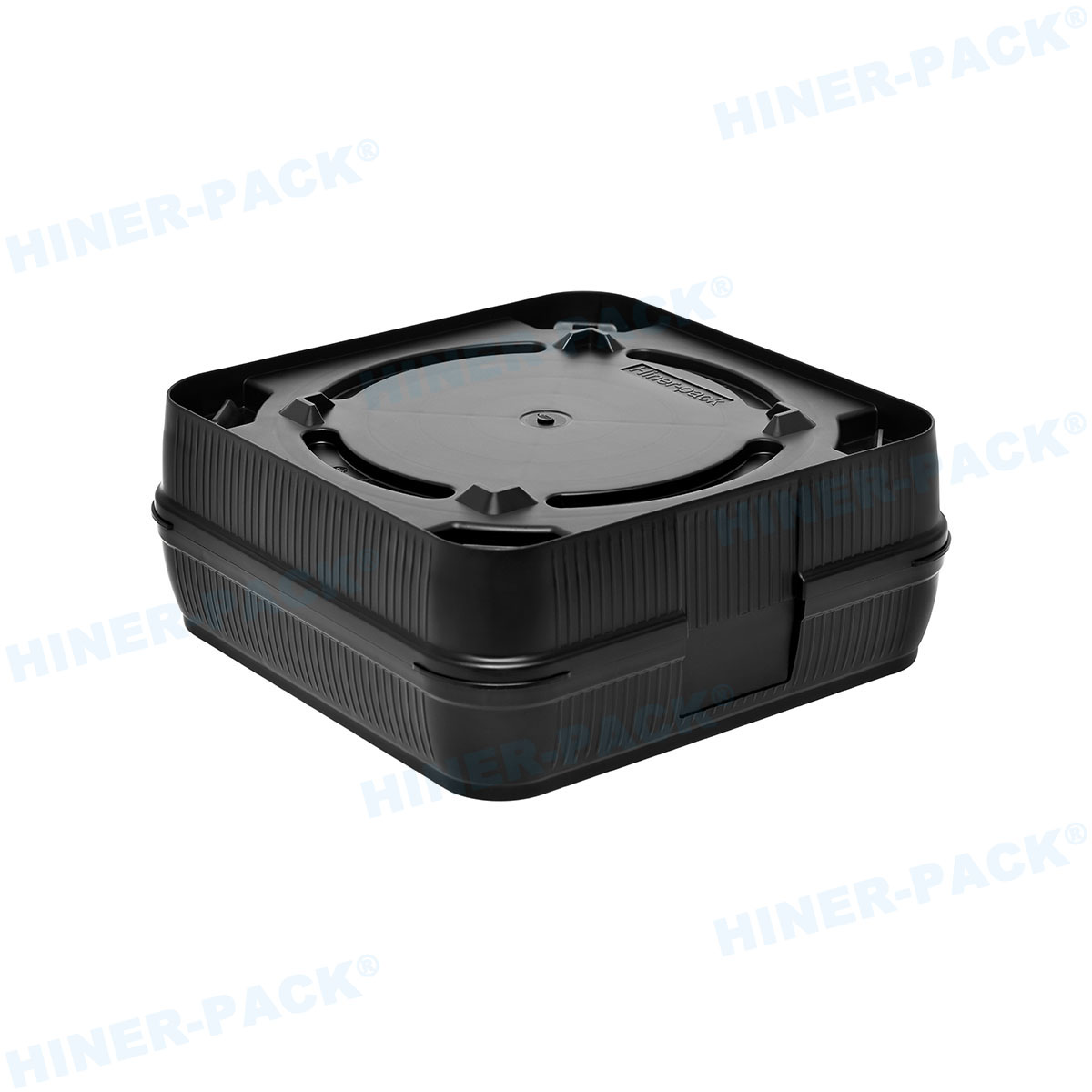
Design Features of Reliable Stackable Trays
Not all stackable trays are created equal. Key design elements ensure secure stacking and component protection.
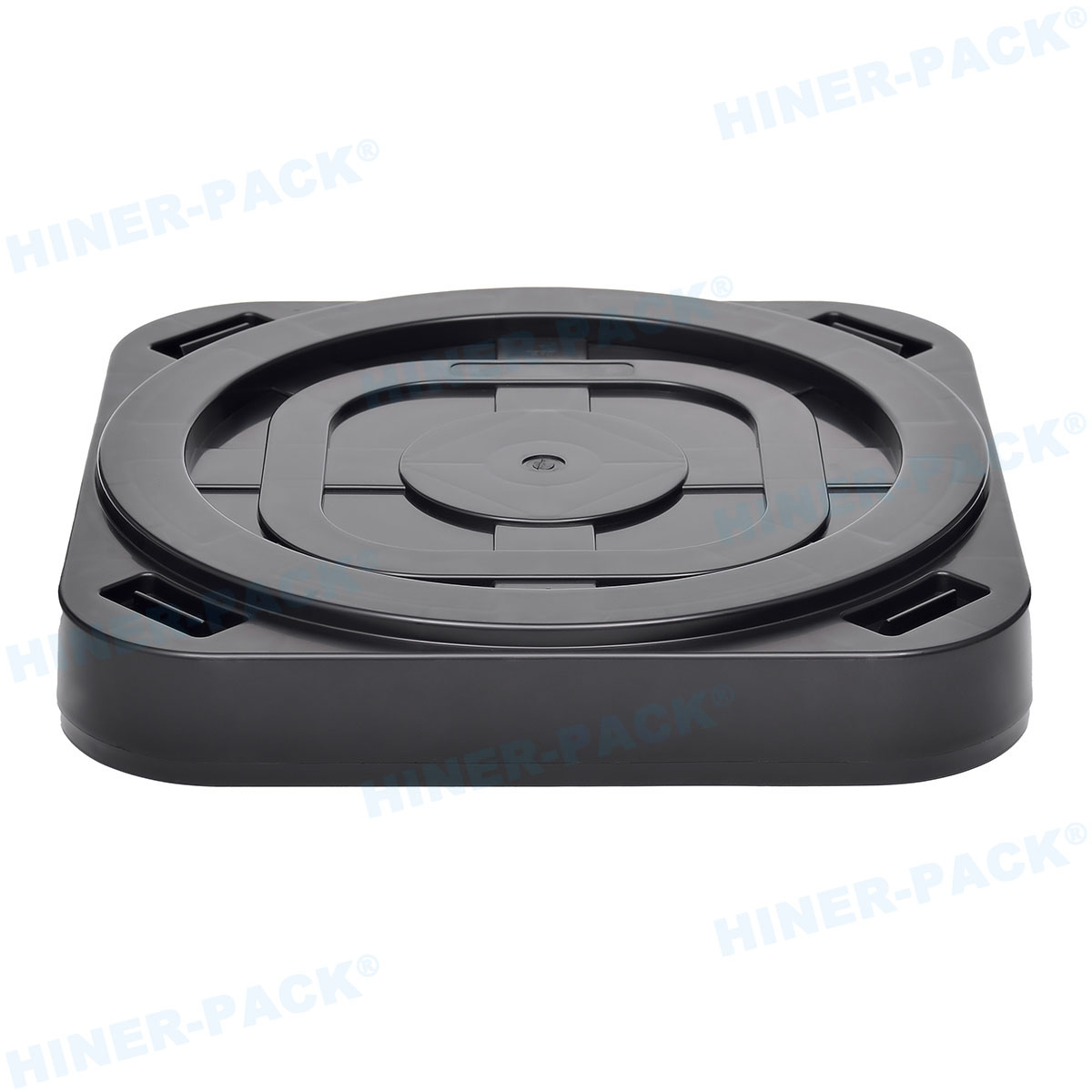
Interlocking Stacking Features
This is the core of safe stackability. Designs include:
Corner Posts/Pillars: Vertical posts at the corners provide structural support and alignment.
Nesting Rims: A lip on the bottom tray interlocks with a recess on the top tray, preventing lateral slippage.
Weight Distribution: The design ensures the weight of the stack is borne by the tray frame, not the ICs inside.
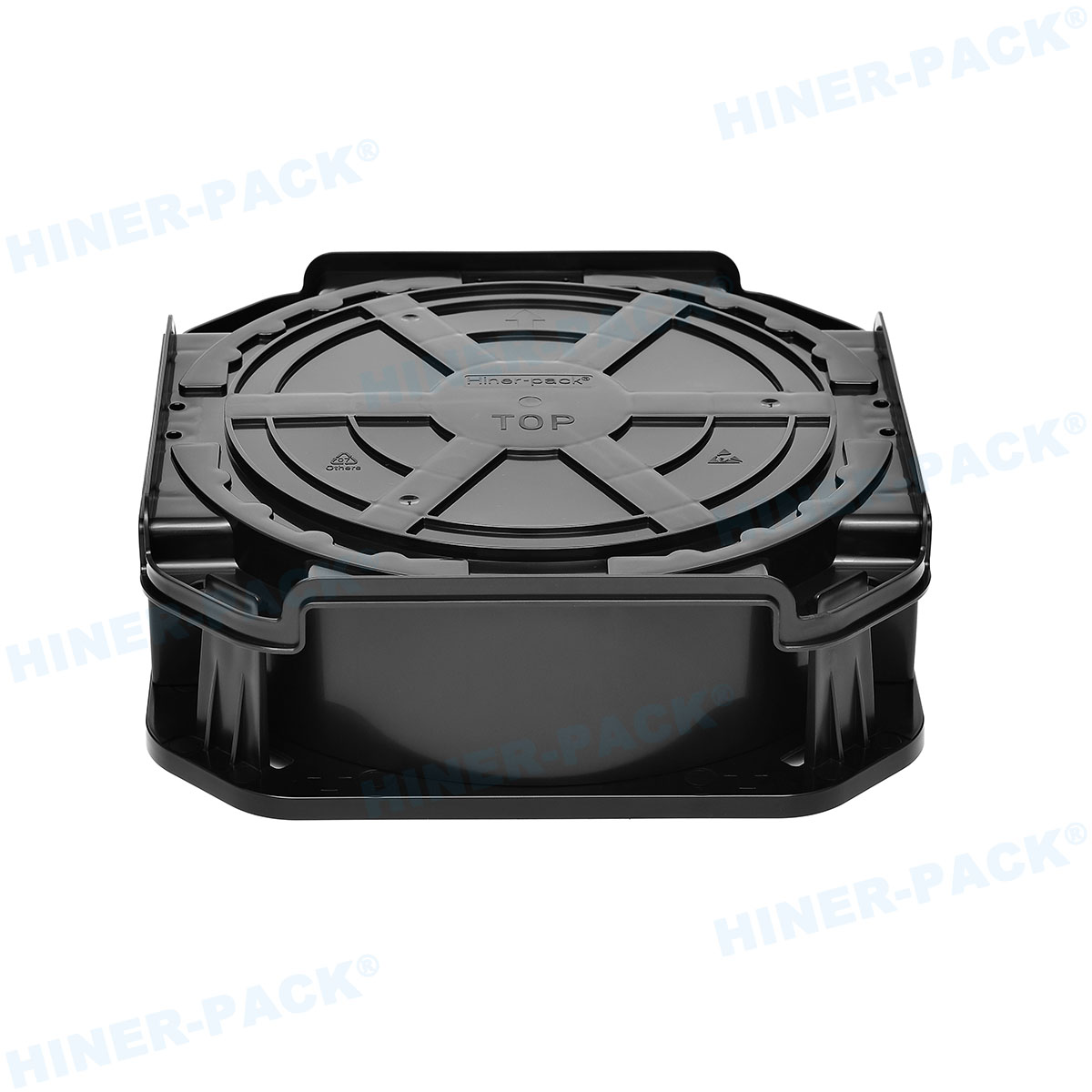
Cavity Design and Component Security
The individual pockets that hold the ICs must be precisely molded.
Snug Fit: Holds devices firmly to prevent "tombstoning" or shifting during transport.
Lead Protection: Cavities are designed to protect delicate pins or leads from bending.
Ease of Pick-and-Place: Design allows for easy vacuum pickup by automated equipment.
Compatibility and Identification
JEDEC Standards: Compliance with specific outlines (MO-XXX) ensures global compatibility.
Barcode/Data Matrix Areas: Flat surfaces for labels enable traceability.
Robot Handling Features: Flanges and notches designed for robotic arms and conveyor systems.
Applications Across the Semiconductor Workflow
The right stackable JEDEC tray options are used in multiple stages of production.
Post-Assembly and Test
After wafer dicing and die attachment, ICs are placed in trays for electrical testing, inspection, and marking.
Transport and Logistics
Stackable trays are ideal for shipping ICs between contract manufacturers, distributors, and OEM customers. They secure parts in transit and simplify unloading.
Long-Term and Buffer Storage
In warehouses, the space-saving benefit of stackable trays is fully realized, allowing for high-density, organized storage of components.
Selecting the Right Tray: A Supplier Perspective
Choosing a reliable supplier is as important as selecting the tray specification. A partner like Hiner-pack provides value through:
Material Expertise: Guidance on selecting the correct material for your ESD and thermal requirements.
Precision Manufacturing: Consistent cavity dimensions and stacking feature quality to ensure performance.
Customization: Ability to provide custom solutions for non-standard devices or unique process needs.
Supply Chain Reliability: Consistent quality and on-time delivery to keep your production line moving.
Selecting the appropriate stackable JEDEC tray options is a fundamental decision for protecting product yield and ensuring operational efficiency. By understanding the material properties, critical design features, and application requirements, manufacturers can make informed choices. Partnering with an experienced supplier such as Hiner-pack ensures access to high-quality, reliable trays that meet industry standards and support a smooth, damage-free logistics chain from factory to end-user.
Frequently Asked Questions (FAQs)
Q1: What is the main difference between conductive and dissipative stackable JEDEC trays?
A1: Conductive trays have very low electrical resistance (<1 10="" x="">
Q2: Can I stack trays from different manufacturers together?
A2: It is not recommended. Even if they meet the same JEDEC outline, slight variations in stacking feature dimensions can cause misalignment, instability, or stress on the components. For safety and stability, use trays from the same manufacturer and production batch for stacking.
Q3: How do I clean stackable JEDEC trays, and how often?
A3: Trays should be cleaned with deionized water or isopropyl alcohol and lint-free wipes. Ultrasonic cleaning is also effective for some materials. Frequency depends on the environment; clean them when visual inspection shows particulate contamination or according to a scheduled preventive maintenance plan to avoid yield loss.
Q4: Are there weight limits for stacking loaded trays?
A4: Yes. While trays are designed for stacking, exceeding a recommended height (often 5-10 trays high, depending on design and IC weight) can cause compression at the bottom. Always consult the manufacturer's specifications and consider the total weight of the ICs when determining safe stack height.
Q5: How do I know which JEDEC tray outline (MO-XXX) I need?
A5: The tray outline is determined by the package type and dimensions of your IC (e.g., QFP, BGA, SOIC). The package vendor typically specifies the appropriate JEDEC outline. You can also measure your packaged device and consult JEDEC publication MO-095, or work with your tray supplier who can match the device to the correct standard outline.


!")