A single millimeter of error can halt a high-speed assembly line. In semiconductor handling, consistency isn’t just beneficial; it’s the foundation of modern manufacturing. This consistency is codified in the precise world of JEDEC tray dimensions. For engineers, procurement specialists, and operations managers, understanding these specifications is the difference between seamless production and costly downtime. These standardized measurements ensure that a tray from any supplier interfaces perfectly with automated equipment worldwide. Ignoring the nuances of these dimensions leads to misfeeds, device damage, and frustrated operators. Let’s break down what really matters when it comes to these critical specifications and how getting them right safeguards your entire process.
What Are JEDEC Tray Dimensions and Why Do They Matter?
JEDEC tray dimensions refer to the complete set of standardized measurements that define the physical form and fit of carrier trays used for semiconductors. Governed by JEDEC (Joint Electron Device Engineering Council), these specs are not suggestions. They are strict engineering requirements.
The core purpose is interoperability. A factory in Malaysia, a test house in Texas, and an assembly plant in Germany all use different machines. However, if each uses trays built to the same JEDEC outline, the components flow smoothly between them. This global language of physical packaging eliminates guesswork and custom adapters.
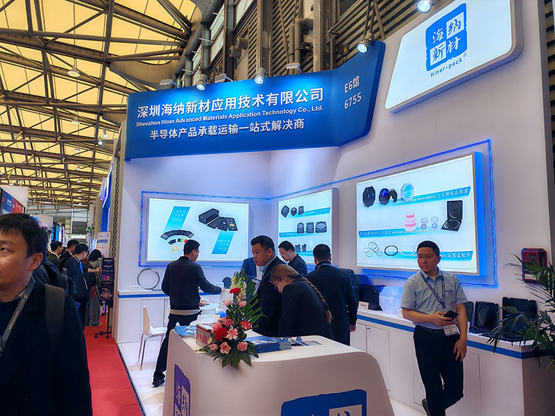
For a company like Hiner-pack, manufacturing to these dimensions is the baseline. It’s the absolute minimum requirement to enter the market. True value, however, comes from mastering the tolerances within those specs.
Decoding the Key Measurements in a Datasheet
A JEDEC standard sheet is dense with numbers. Knowing which ones are critical for functionality is key.
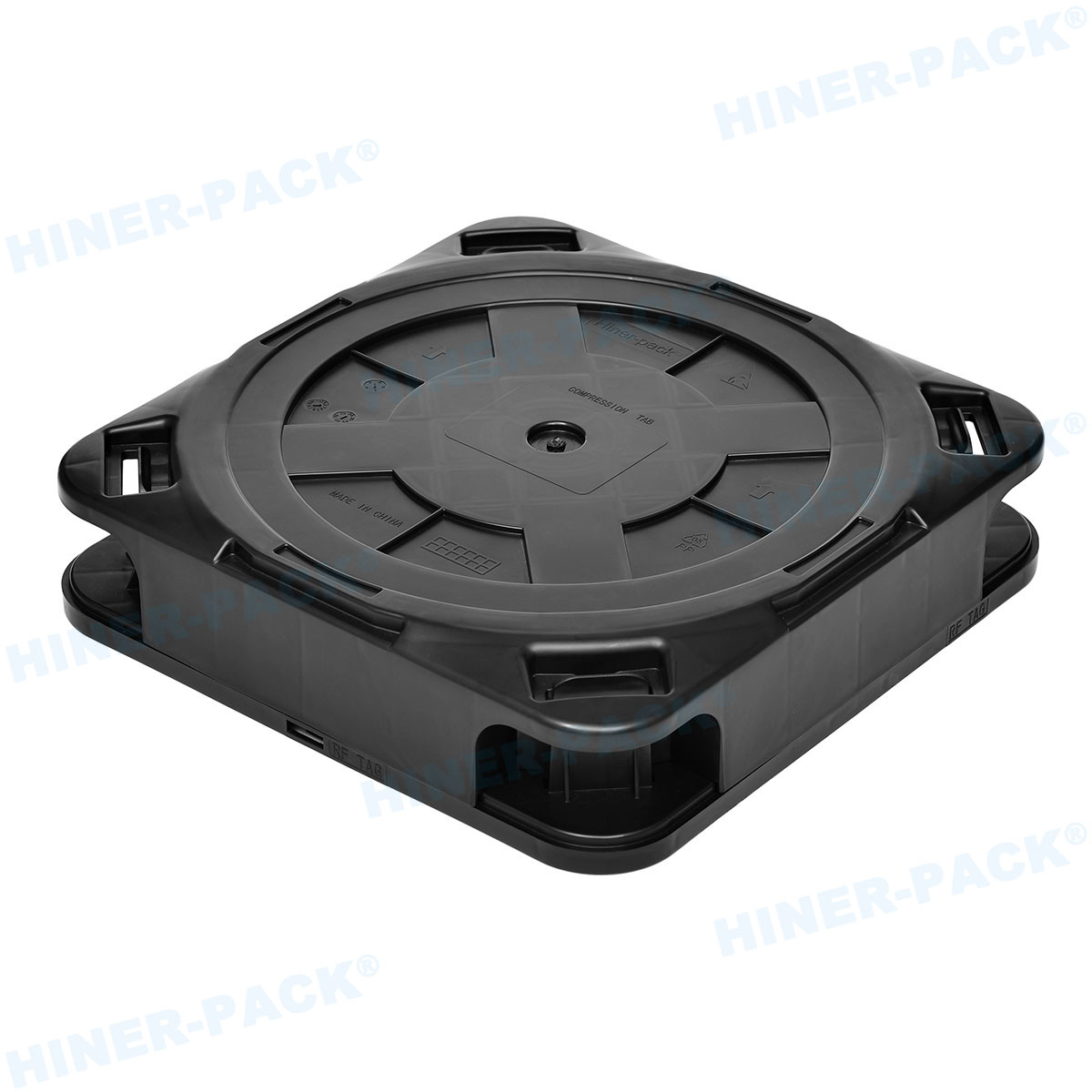
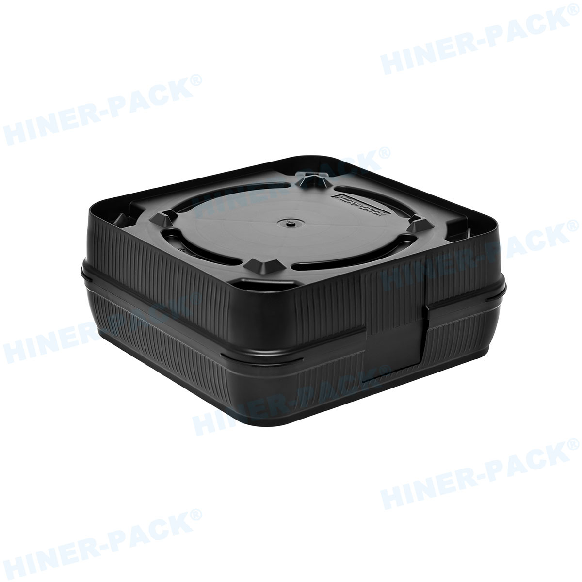
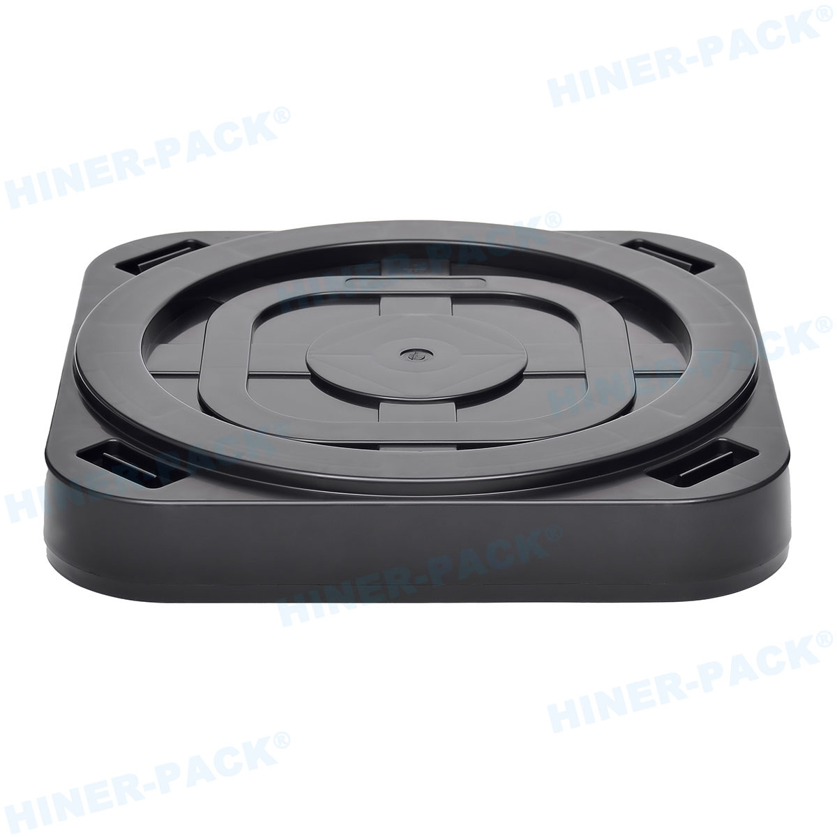
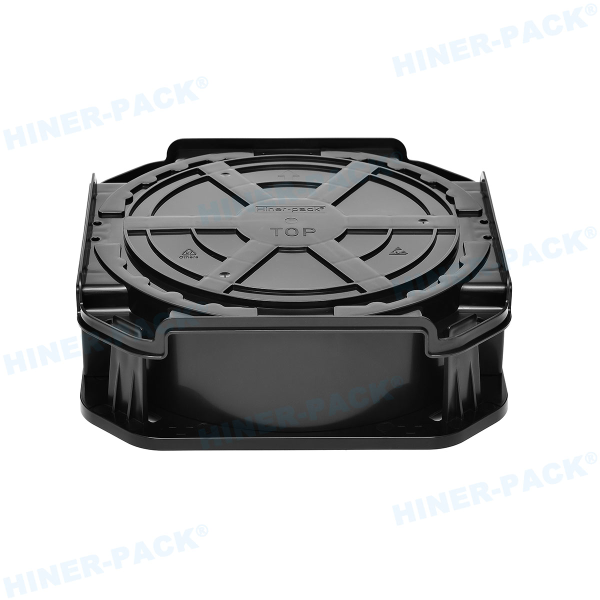
The overall outline, like “MO-048” or “MO-095,” defines the tray’s footprint—its length (L) and width (W). This must match the slots in your automated handling equipment and storage systems.
Cavity size and pitch are paramount. The pocket that holds the device has specific X, Y, and Z dimensions. The pitch (distance between cavity centers) determines how many units fit on a tray. A slight error here can cause devices to sit too tight or too loose.
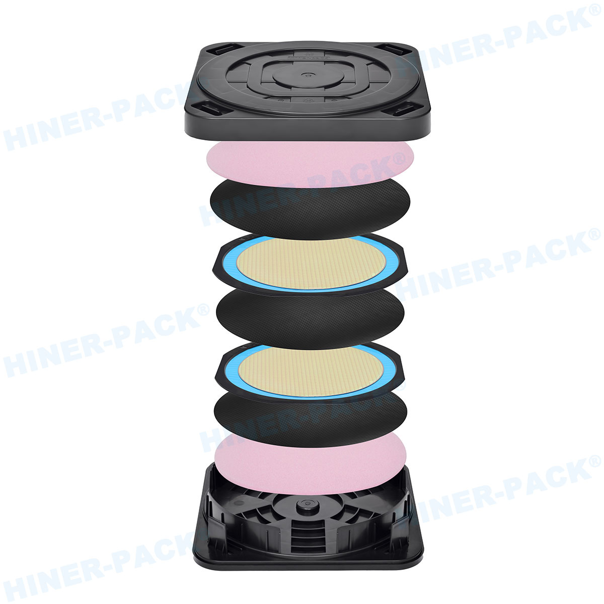
Stack height and overall tray height are crucial for stability. These dimensions ensure trays nest or stack securely without putting pressure on the components inside during transport or automated unstacking.
Features like chamfers, pick holes, and robot access flanges all have defined positions and sizes. These allow grippers and mechanisms to engage the tray reliably.
The Role of Material and Manufacturing in Holding Dimension
A perfect design means nothing if the tray warps. JEDEC tray dimensions assume the part is made from a suitable material and processed correctly.
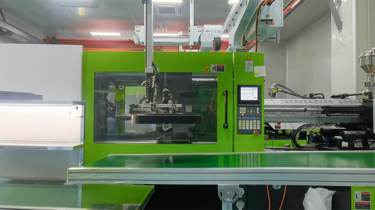
Materials like polycarbonate (PC) and PEEK have different shrinkage rates during molding. A reputable manufacturer like Hiner-pack accounts for this in the mold design. The goal is a tray that cools to the exact dimensions specified, not just when it’s new.
Thermal stability is part of dimensional integrity. Trays may be exposed to baking cycles. A low-quality tray can warp at 125°C, permanently altering its critical dimensions and ruining its compatibility.
Consistency across a production lot is the real test. The tenth tray from a mold should be dimensionally identical to the ten-thousandth. Hiner-pack achieves this through controlled processes and rigorous quality checks, measuring sample trays against master gauges.
How to Select the Correct Tray Based on Your Component
Choosing the right tray isn’t just about picking a standard. It’s a matching process.
Start with your component’s mechanical drawing. Note the package type (e.g., QFN, BGA, SOP) and its exact length, width, and thickness. This is your starting point.
Cross-reference this with JEDEC publication MO-048, which covers many common outlines. Your component supplier may also recommend a specific tray outline code.
Don’t just match the cavity size. Consider the lead or ball clearance. Cavities are designed with a small nominal clearance (e.g., 0.2mm per side) to allow for easy pick-up without excessive movement.
For non-standard parts, the external JEDEC tray dimensions for a standard outline can often be used with a custom cavity. This maintains machine compatibility while accommodating a unique device.
Compatibility with Automation and Handling Equipment
This is where dimensions translate into performance. Every measurement has a mechanical purpose.
The overall length and width must align with conveyor guides and magazine slots. Even a 0.5mm overhang can cause a jam in a high-speed loader.
Robot access flanges, often called “ears,” have a defined thickness and undercut. A gripper claw is designed to slide into this space. If the flange is too thick or the undercut too shallow, the pickup fails.
Stack height directly impacts the capacity of a stacker/unstacker module. An inconsistent stack height can cause an automated handler to miscount trays or apply incorrect pressure.
At Hiner-pack, we test our trays not just with calipers, but in mock-ups of actual handling equipment. This functional validation is as important as the paper spec.
Why Not All Suppliers Deliver True JEDEC Compliance
The market is full of trays that claim JEDEC compliance. The reality can be different.
Some suppliers use worn-out molds that produce trays at the very edge of the tolerance band. While technically “within spec,” these trays may stack poorly or feed inconsistently.
The focus might be only on critical cavity dimensions, while neglecting less obvious ones like corner radii or identification marker spots. This can cause unexpected issues in niche applications.
True compliance means adhering to every dimension and material property called out in the standard. It requires investment in precision tooling and process control. Hiner-pack’s commitment is to full-spectrum compliance, ensuring every tray performs predictably in the field.
Common Mistakes in Measuring and Specifying Trays
Engineers sometimes face issues that stem from basic misunderstandings of the standards.
Using a standard caliper on a flexible plastic tray can yield inaccurate readings. Proper measurement requires flat surfaces and pin gauges for cavities.
Confusing internal cavity dimensions with the overall device size. Remember, the cavity is always slightly larger than the component.
Assuming all trays for a “24x24mm BGA” are the same. Different JEDEC outlines (like MO-150 vs. a custom) may fit the same device but have different external footprints, making them incompatible with your machine’s magazine.
Not accounting for cumulative tolerance in a stack. A stack of 50 trays, each at the upper limit of the thickness tolerance, might be too tall for a fixed-height shipping carton or storage rack.
Mastering JEDEC tray dimensions is a technical discipline. It moves packaging from a simple commodity purchase to a strategic part of manufacturing engineering. By focusing on the precise measurements, their purpose, and the manufacturing quality behind them, you eliminate a major source of production risk. The goal is a tray that disappears into the process—unnoticed, reliable, and perfectly dimensional. For partners like Hiner-pack, delivering that level of invisible reliability is what defines a true quality supplier in the semiconductor space.
Frequently Asked Questions (FAQ)
Q1: Where can I find the official JEDEC tray dimension standards?
A1: The primary source is JEDEC itself. Publication MO-048 covers many common tray outlines. You need to purchase these documents from the JEDEC website. Alternatively, reputable suppliers like Hiner-pack have these standards and can guide you to the correct outline based on your component details.
Q2: How do I measure a JEDEC tray to verify its dimensions?
A2: Use precision tools like digital calipers on a flat, stable surface. For critical external dimensions (L, W, H), ensure the tray is not warped. For cavity depths and small features, pin gauges are more accurate. The best practice is to request a Certificate of Conformance or dimensional report from your supplier.
Q3: Can the tray material affect the final dimensions in use?
A3: Absolutely. Low-grade materials can creep or warp under load or temperature. A tray might measure correctly off the shelf but deform when stacked high in a warm warehouse. Always specify trays made from dimensionally stable, temperature-resistant materials for critical applications.
Q4: Is it safe to mix trays from different suppliers if they claim the same JEDEC code?
A4: Proceed with caution. While they should be identical, variations in material and molding can lead to subtle differences in stack height or flange geometry. It’s advisable to qualify a new supplier’s trays in your specific equipment before full-scale adoption, even if the code matches.
Q5: What if my component doesn’t fit any standard JEDEC tray dimensions?
A5: You have two main paths. First, consult with experts like Hiner-pack. A minor non-standard feature might fit a standard cavity. Second, consider a “custom external” tray. This keeps the critical external JEDEC tray dimensions (footprint, stack height) standard while modifying the internal cavities for your device, preserving automation compatibility.