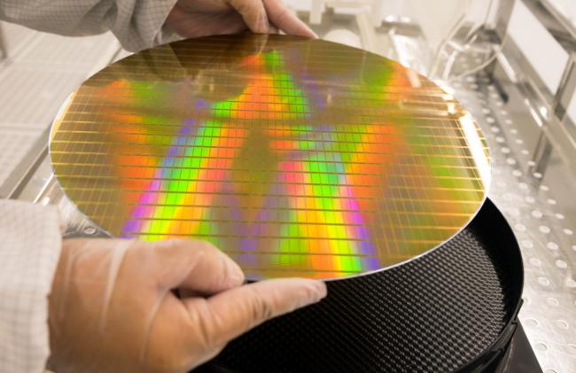
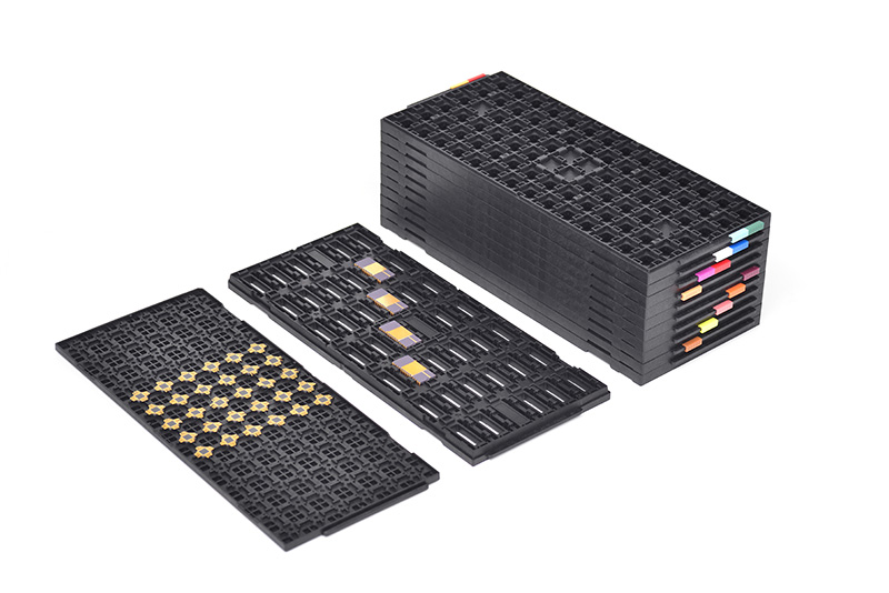
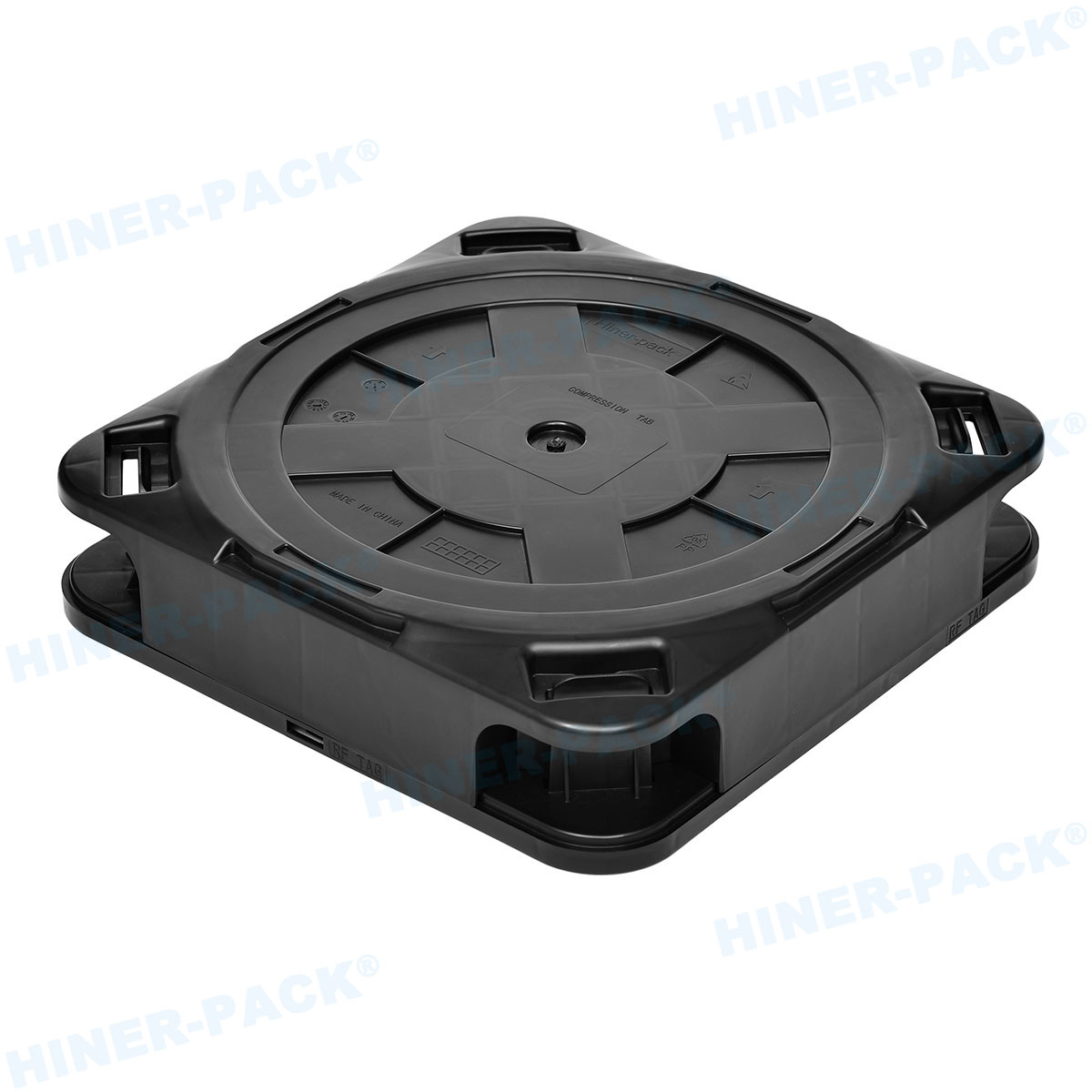
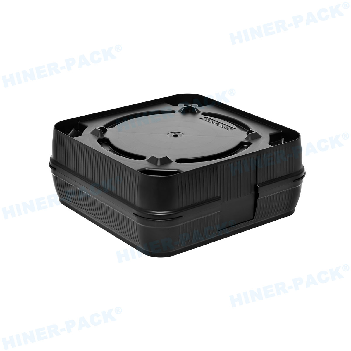
In the semiconductor backend supply chain, the JEDEC matrix tray is the fundamental unit of transport and processing. While the external dimensions of these trays are strictly governed by JEDEC standards (specifically the MO-series configurations), the internal topography—the pocket design—often requires precise engineering intervention. As package geometries evolve into complex System-in-Package (SiP), ultra-thin QFNs, and fragile MEMS configurations, off-the-shelf trays frequently fail to meet strict yield requirements.
For process engineers and procurement managers, investing in Custom JEDEC tray design is not merely a logistical choice; it is a critical component of Quality Assurance. A poorly designed tray leads to component migration, bent leads, and pick-and-place errors that can stall high-speed automated lines. This article provides a comprehensive technical breakdown of the criteria required to engineer, validate, and source high-performance custom carriers.
1. The Geometry of Retention: Beyond Standard Pockets
The primary driver for moving away from standard catalog trays is the mismatch between the device tolerance and the pocket fit. Standard trays are designed with loose tolerances to accommodate a range of package variances. However, for precision components, "loose" translates to movement.
When engineering a Custom JEDEC tray design, three geometric factors must be calculated with micron-level precision:
The X/Y Clearance and Pocket Fence
The gap between the component body and the tray pocket wall (the fence) dictates stability. Excessive clearance allows the component to gain momentum during transit vibration, leading to impact damage. Conversely, insufficient clearance causes jamming during gravity-fed testing or robotic insertion. A custom design typically targets a clearance of 0.1mm to 0.2mm, depending on the package's coefficient of thermal expansion (CTE).
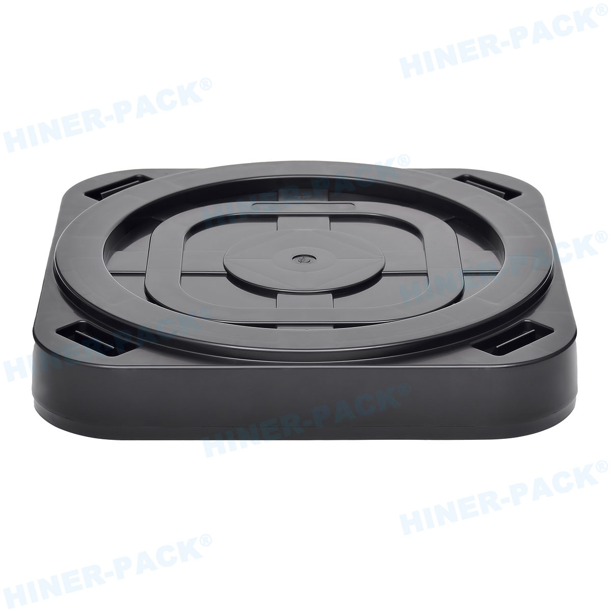
Z-Height and Pedestal Support
For Ball Grid Array (BGA) and Chip Scale Package (CSP) devices, the solder balls must never bear the weight of the device. Custom designs incorporate a "pedestal" or "shelf" system that supports the package body on its perimeter or corners, leaving the ball array suspended. The depth of this suspension is critical; if it is too shallow, the balls touch the tray floor; if too deep, the overall tray stacking height (Stacking Pitch) may be compromised.
Draft Angles and Ejection Mechanics
The internal draft angle of the pocket walls is essential for the injection molding process, but it also impacts component retrieval. A steep draft angle ensures the device centers itself (self-alignment) when dropped into the tray. However, if the angle is too aggressive, it reduces the effective contact area at the bottom of the pocket. Advanced simulation software is used to balance mold release requirements with component stability.
2. Material Science: Selecting Polymers for Thermal and ESD Performance
The physical geometry is only effective if the material maintains its integrity under stress. Semiconductor manufacturing environments subject trays to extremes—from baking ovens to cryogenic testing. The material selection process for a Custom JEDEC tray design generally falls into three distinct categories based on thermal deflection temperature (HDT).
Low-Temp / Shipping Grade (< 60°C): Typically comprised of PS (Polystyrene) or ABS composites. These are cost-effective for one-way shipping but will deform if introduced to bake-out processes.
Medium-Temp / Universal Grade (125°C - 140°C): The most common category, often utilizing MPPO (Modified Polyphenylene Oxide) or PPE (Polyphenylene Ether). These materials offer excellent dimensional stability and are suitable for standard moisture removal bakes.
High-Temp / Process Grade (150°C - 180°C+): For rigorous testing environments, materials like PES (Polyethersulfone) or PSU (Polysulfone) specifically reinforced with glass fiber or carbon fiber are required. These materials resist warping even under prolonged heat exposure.
Furthermore, Electrostatic Discharge (ESD) protection is non-negotiable. Carbon powder or carbon fiber is compounded into the base polymer to create a conductive or static-dissipative matrix. The target surface resistance is typically between 10^5 and 10^9 ohms. Manufacturers like Hiner-pack utilize advanced compounding techniques to ensure that these ESD properties remain consistent across the entire surface of the tray, preventing "hot spots" where static could accumulate.
3. The Challenge of Warpage and Flatness Control
Warpage is the enemy of automation. A JEDEC tray that bows or twists will cause vacuum pickup heads to miss components or, worse, crush them. The industry standard tolerance for flatness is typically 0.76mm (0.030 inches), but modern high-density lines often demand flatness better than 0.50mm.
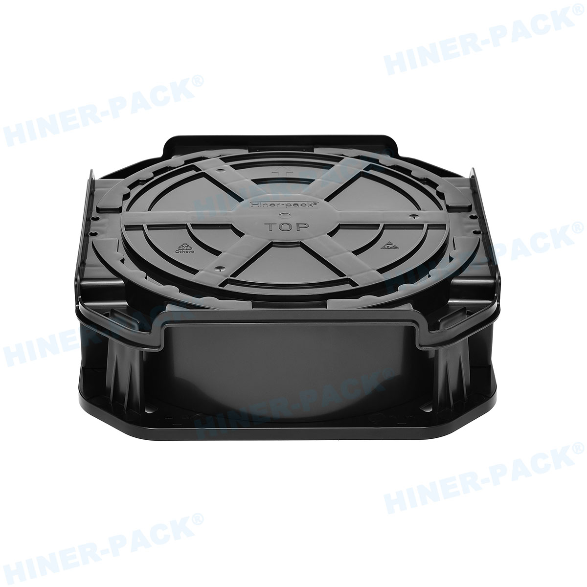
Achieving this in a Custom JEDEC tray design requires sophisticated mold flow analysis before steel is ever cut. Engineers must predict how the molten plastic will cool and shrink. Ribbing structures on the underside of the tray are not just for strength; they are flow leaders designed to distribute stress evenly. If the wall thickness varies too drastically between the pocket area and the frame, differential cooling will induce permanent warp.
This is where partnering with an experienced manufacturer is vital. Companies such as Hiner-pack employ rigorous Coordinate Measuring Machine (CMM) validation protocols to verify flatness metrics post-molding and post-baking, ensuring the tray retains its shape throughout its lifecycle.
4. Automation Integration and Vision Systems
A custom tray does not exist in a vacuum; it must interface with handlers, testers, and tape-and-reel machines. The design must accommodate the specific "fingers" or grippers of the equipment.
Through-Holes and Vacuum Ports
Some automated test equipment (ATE) requires access to the underside of the device while it sits in the tray. Custom designs can incorporate precise through-holes in the center of each pocket. This allows a pusher pin to elevate the device for pickup, or allows a sensor to read a 2D matrix code on the bottom of the package.
Vision System Contrast
Optical inspection systems rely on contrast to detect device presence and orientation. The surface finish of the custom tray plays a role here. A matte texture is often preferred over a glossy finish to reduce glare from ring lights, allowing the camera to clearly distinguish the edge of the package from the edge of the pocket.

5. The Proto-typing and Tooling Lifecycle
Implementing a Custom JEDEC tray design involves a capital expenditure on mold tooling. To mitigate risk, a phased approach is recommended.
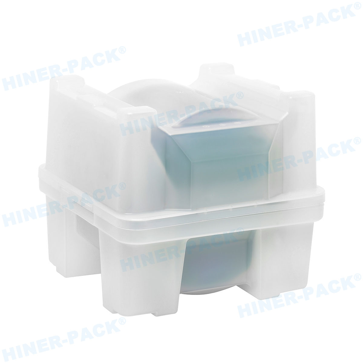
Phase 1: 3D Printing / Machining. Before committing to a steel mold, high-resolution SLA printing or CNC machining of a specific material block can verify the pocket fit. While these prototypes cannot withstand high temperatures, they confirm the X/Y/Z dimensions physically.
Phase 2: Soft Tooling. For smaller runs or market testing, aluminum molds can be cut faster and cheaper than production steel. They serve to validate the injection molding process parameters.
Phase 3: Hard Tooling. For mass production, hardened steel molds (P20 or H13 steel) are necessary to withstand the abrasive nature of carbon-filled plastics and run millions of cycles without degradation.
6. Strategic Sourcing and Supply Chain Resilience
The semiconductor industry is cyclical, and tray shortages can bottleneck shipment. When establishing a supply chain for custom trays, one must consider the manufacturer's capacity for raw material storage and mold maintenance.
Because custom molds are proprietary, the buyer usually owns the tooling. However, the maintenance of that tooling—cleaning vents, polishing surfaces, and repairing gate wear—falls to the manufacturer. It is imperative to select a vendor with in-house tooling capabilities. Hiner-pack has demonstrated capability in managing the full lifecycle of custom trays, from the initial CAD design and mold flow simulation to the final mass production and quality control.
Furthermore, global logistics require that these trays meet international restrictions on hazardous substances (RoHS and REACH). Ensuring your Custom JEDEC tray design utilizes certified, compliant resins prevents costly compliance failures at customs borders.
The transition from standard to custom JEDEC trays marks a maturity point in a semiconductor product's lifecycle. It signifies that the device's value and precision requirements exceed the capabilities of generic packaging. By meticulously engineering the pocket geometry, selecting the appropriate thermal and ESD materials, and ensuring rigid flatness controls, manufacturers can significantly increase yield and throughput.
Success in this arena requires a collaborative engineering effort between the device manufacturer and the packaging partner. With the right design and a robust manufacturing strategy, the humble matrix tray transforms from a simple carrier into a precision engineering tool that safeguards the most critical components of the modern digital world.
Frequently Asked Questions (FAQ)
Q1: What is the standard temperature rating for a "High-Temp" JEDEC tray?
A1: High-temperature JEDEC trays are typically rated for continuous use at 150°C, with short-term excursions up to 180°C permitted depending on the specific resin blend (such as carbon-fiber-reinforced PES or PSU). This rating allows the trays to pass through standard bake-out ovens used for moisture removal without warping or outgassing.
Q2: How does a custom JEDEC tray design improve automation yield compared to standard trays?
A2: Standard trays often have wider tolerances to fit multiple package variations, which allows devices to shift or rotate. This movement causes pick-and-place robots to mishandle the component. A Custom JEDEC tray design tightens the pocket tolerance to restricting movement to typically less than 0.2mm, ensuring the device is always in the exact coordinates expected by the robot.
Q3: What is the difference between Surface Resistance and Volume Resistance in tray materials?
A3: Surface resistance measures the ability of the tray's surface to dissipate a charge, which is crucial for immediate ESD protection. Volume resistance measures the material's inherent conductivity through its thickness. For JEDEC trays, surface resistance is the primary specification, typically targeting the dissipative range of $10^5$ to $10^{9}$ ohms to safely bleed off static charges without creating a rapid discharge event.
Q4: Can I modify an existing standard JEDEC mold to create a custom tray?
A4: Generally, no. Injection molds are complex steel assemblies with integrated cooling channels and ejection pins specific to the pocket geometry. While it is sometimes possible to use interchangeable inserts for the pocket area in a modular mold base, creating a truly custom pocket design usually requires a new tooling set to ensure proper flow and cooling.
Q5: How do I ensure my custom tray design is stackable with other standard trays?
A5: JEDEC Publication 95 defines the external outline and stacking features of the matrix tray. Regardless of the internal pocket customization, the external frame, alignment tabs, and stacking steps must strictly adhere to these JEDEC outline dimensions. A professional design partner will ensure the "envelope" dimensions remain compliant while customizing the internal storage area.