1. Material Science: ESD-Safe Foam Formulations
The foundational property of any anti-static foam trays is controlled electrical conductivity. Three primary material classes dominate the industry:
Polyurethane (PU) Foam with Static-Dissipative Additives
Open-cell PU foam is widely used due to its resilience, conformability, and low compression set. Static-dissipative grades incorporate carbon powder or inherently conductive polymers to achieve surface resistivity between 10⁶ and 10⁹ ohms/sq (per ANSI/ESD S11.11). These materials provide a controlled discharge path with decay time<0.05 1="" seconds="" from="">
Density: 1.5–4.0 lb/ft³ (24–64 kg/m³) for varying cushioning requirements.
Compression set:
<10% 50="" at="">Outgassing: Total mass loss
<0.1% per="" astm="" e595="">
Polyethylene (PE) Foam – Conductive & Dissipative Grades
Closed-cell PE foam offers superior chemical resistance and low particle generation, making it ideal for cleanroom environments (ISO Class 5–7). Conductive PE grades (surface resistivity 10³–10⁵ ohms/sq) are used for highly sensitive components such as GaAs devices or MEMS sensors. Cross-linked PE provides exceptional tear strength and maintains dimensional stability across temperature ranges of -40°C to +80°C.
Ethylene Vinyl Acetate (EVA) Copolymer Foam
EVA offers a balance of flexibility and durability, often specified for high-volume tray applications requiring repeated handling. Anti-static EVA formulations incorporate permanent antistatic agents (non-blooming) to maintain consistent performance without surface migration that can cause contamination.
Leading suppliers like Hiner-pack offer hybrid foam trays combining layers of different materials—for example, a conductive PU base for ESD protection with a soft, dissipative top layer to prevent die scratching.
2. Surface Resistivity and ESD Performance Metrics
ESD-safe packaging must meet ANSI/ESD S20.20 and IEC 61340-5-1 standards. For anti-static foam trays, the critical parameters are:
Surface resistivity: 10⁶ to 10⁹ ohms/sq (dissipative range) for sensitive devices; 10³ to 10⁵ ohms/sq (conductive) for extremely ESD-sensitive components like RF transistors.
Volume resistivity: Typically 10⁴ to 10⁸ ohm-cm, ensuring bulk conductivity through the foam thickness.
Static decay time:
<2 seconds="" per="" federal="" test="" method="" 101c="">Triboelectric charge generation:
<100 volts="" when="" rubbed="" against="" common="" cleanroom="" materials="">
Regular verification using concentric ring electrodes (per ASTM D257) ensures ongoing compliance. Facilities processing Class 0 ESD-sensitive components (sensitivity<100v) require="" conductive="" foam="" with="" verified="" charge="" generation="">
3. Particulate Contamination Control: Cleanroom Compatibility
Semiconductor packaging requires foam trays that do not introduce particles that could cause die attach voids or wire bonding failures. Key specifications:
Non-shedding foam cells: Closed-cell structures or fully encapsulated open-cell foams prevent release of loose particles. Liquid silicone rubber (LSR) coatings can encapsulate PU foam, reducing particle counts by 95% compared to uncoated foam.
Ionic contamination: Foam must pass extractable ion testing per IPC-TM-650, with chloride and sodium levels below 0.1 µg/cm² to prevent corrosion of exposed metallization.
Cleanroom classification: Trays intended for ISO Class 5–6 environments must be manufactured, cleaned, and packaged under laminar flow with HEPA filtration. Double-bagging in ESD-safe shielding bags with vacuum sealing is standard.
Field data from a major OSAT (outsourced semiconductor assembly and test) provider showed that switching to low-particle anti-static foam trays reduced die attach rework rates by 1.2%—equivalent to $480,000 annual savings for a high-volume facility.
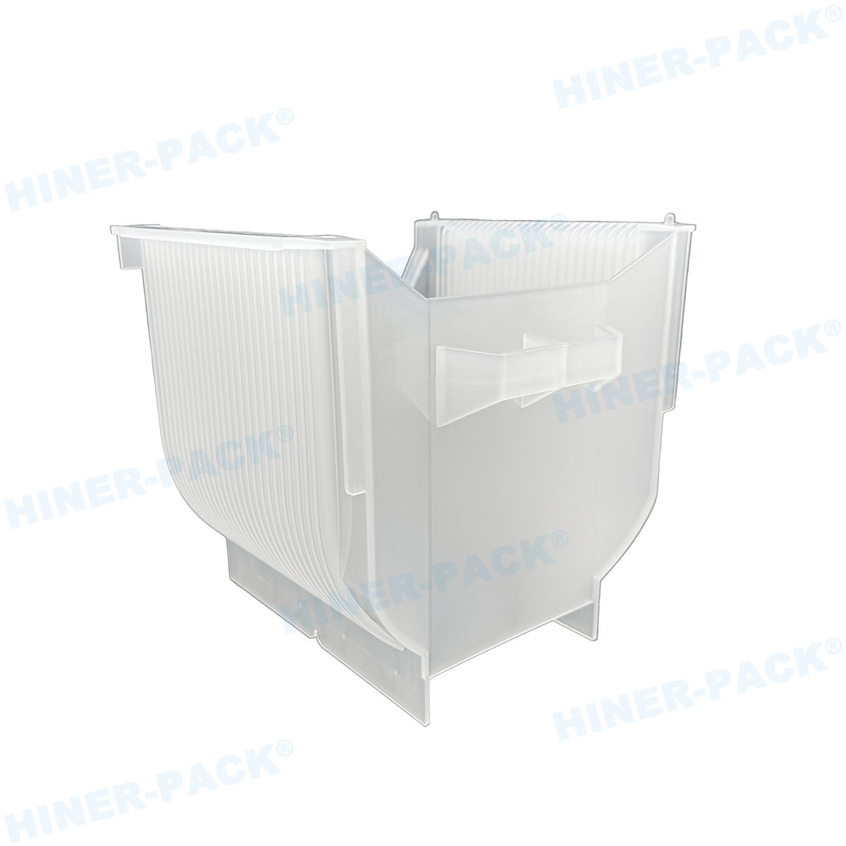
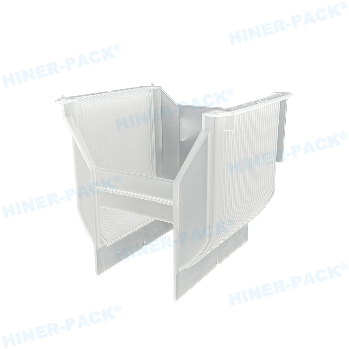
4. Mechanical Engineering: Die-Cut Precision and Pocket Design
Pocket geometry directly impacts component stability and damage prevention. Precision die-cutting using hardened steel rule dies or CNC waterjet ensures:
Pocket tolerances: ±0.1 mm for 0.5 mm pitch components, ±0.2 mm for larger packages. Undersized pockets cause component stress; oversized pockets allow shifting during transport.
Chamfered edges: 0.5–1.0 mm radius at pocket entry prevents snagging of delicate leads (e.g., QFN, BGA).
Depth control: Pocket depth equal to component height plus 0.5 mm clearance ensures components remain below tray rim for stacking.
Anti-rotation features: Asymmetric pocket shapes or indexing notches prevent incorrect component orientation during automated pick-and-place.
For wafer-level components, trays may incorporate gel-based inserts or silicone elastomer pads to absorb shock and accommodate height variations.
5. Thermal Stability and Outgassing Control
Components may undergo thermal cycling during transport or storage (e.g., cold chain for moisture-sensitive devices). Foam trays must maintain structural integrity across specified temperature ranges:
Operating range: -40°C to +85°C typical; some applications require -65°C to +125°C.
Outgassing limits: NASA ASTM E595 requires total mass loss
<1.0% and="" collected="" volatile="" condensable="" materials="">Hydrolysis resistance: Polyester-based PU foams degrade in high-humidity environments; polyether-based formulations are preferred for tropical or unconditioned storage.
Advanced fabs now specify outgassing testing using thermal desorption GC-MS to identify trace organic compounds (e.g., plasticizers, flame retardants) that could cause lens fogging in optical sensors or corrosion in MEMS devices.
6. Application-Specific Configurations
Different semiconductor and electronics segments demand tailored foam tray designs:
Wafer shipping trays: Accommodate 150mm–300mm wafers in FOSB or single-wafer shippers. Trays include precision-machined pockets with raised support rings to minimize contact with active device areas.
Die banks and waffle trays: JEDEC-standard J-STD-033 defines tray dimensions for moisture-sensitive devices. Anti-static foam waffle trays provide individual cavities for die or small components with 0.5–2.0 mm pitch.
PCB assembly trays: Custom foam profiles hold populated PCBs during in-plant transport, with cutouts for connectors, tall components, and solder ball arrays.
Automated handling trays: Designed with registration holes and edge rails compatible with surface-mount technology (SMT) equipment feeders and tray stackers.
Hiner-pack provides application engineering services, converting customer CAD data into optimized tray layouts with full tolerance analysis and prototype samples for validation.
7. Quality Assurance and Traceability
For high-reliability sectors (automotive, medical, aerospace), foam trays require full material traceability and statistical process control (SPC) during manufacturing. Typical QA protocols include:
Incoming material certification: Supplier must provide certificates of analysis (COAs) for resistivity, density, tensile strength, and outgassing.
In-process inspection: 100% visual inspection for die-cutting defects (burrs, incomplete cuts, foreign material). Automated vision systems can inspect 60 trays/minute for dimensional conformity.
Lot traceability: Each production lot assigned unique identifier linking to foam batch, die tool, manufacturing date, and test results.
Packaging verification: ESD bag seal integrity testing and vacuum decay testing for moisture-barrier packaging per IPC/JEDEC J-STD-033.
Automotive customers often require IATF 16949 certification for the foam tray supplier, ensuring compliance with advanced product quality planning (APQP) and production part approval process (PPAP) documentation.
8. Sustainability and Recycling Considerations
Increasingly, electronics manufacturers mandate sustainable packaging solutions. Eco-friendly options for anti-static foam trays include:
Recyclable PE foams: Closed-loop recycling programs accept post-industrial scrap.
Bio-based PU foams: Derived from soybean or castor oil, reducing petroleum dependency by 30–50%.
Water-based adhesives: Used for laminated trays, eliminating solvent emissions during manufacturing.
Major semiconductor manufacturers now include sustainability scorecards in supplier evaluations, favoring foam tray vendors with ISO 14001 certification and documented waste reduction programs.
9. Total Cost of Ownership: Custom vs. Stock Trays
While custom anti-static foam trays require upfront tooling costs ($500–$5,000 depending on complexity), TCO analysis often favors customization for medium-to-high volumes:
Damage reduction: Custom pockets reduce component damage by 50–80% compared to generic trays, directly reducing scrap costs.
Automation efficiency: Trays designed for SMT feeders improve pick-and-place yield by 2–5%, reducing placement rework.
Storage density: Optimized tray stacking reduces storage footprint by 30–50%, lowering cleanroom facility costs.
Reusability: Durable foam trays withstand 20–50 cleaning cycles, amortizing initial cost over multiple uses.
A case study from a MEMS sensor manufacturer showed that switching to precision-engineered custom foam trays reduced component damage from 3.2% to 0.4%, achieving payback in 8 months despite higher initial tooling investment.
Frequently Asked Questions (FAQ)
Q1: What is the difference between anti-static, static-dissipative, and conductive foam trays?
A1: Anti-static (or static-dissipative) foam has surface resistivity of 10⁶ to 10⁹ ohms/sq, providing controlled discharge without rapid current flow—ideal for most electronic components. Conductive foam has resistivity below 10⁵ ohms/sq, offering faster discharge for extremely sensitive devices like RF power transistors or GaAs components. The term "anti-static" is often used broadly but technically refers to materials that prevent triboelectric charge generation, while dissipative/conductive materials provide a discharge path.
Q2: How do I select the correct foam density for my application?
A2: Foam density selection depends on component weight, fragility, and handling frequency:
Low density (1.5–2.0 lb/ft³): Light components (
<50g), delicate="" leads="">Medium density (2.5–3.5 lb/ft³): General-purpose assembly trays, components 50–500g, reusable applications.
High density (4.0–6.0 lb/ft³): Heavy components (>500g), frequent manual handling, or where dimensional stability under load is critical.
Q3: Can anti-static foam trays be cleaned and reused?
A3: Yes, but cleaning protocols depend on foam type. Closed-cell PE and EVA foams can be cleaned with isopropyl alcohol (IPA) wipes or ultrasonic cleaning in DI water with mild surfactant, followed by forced-air drying. Open-cell PU foams are more difficult to clean thoroughly and may trap contaminants; they are typically considered single-use or limited-reuse. Reusable trays should undergo periodic ESD verification (resistivity testing) and visual inspection for wear or contamination. Hiner-pack offers validation protocols for customers implementing tray recirculation programs.
Q4: What certifications should I require from an anti-static foam tray supplier?
A4: Essential certifications include: ISO 9001:2015 (quality management), ANSI/ESD S20.20 (ESD program compliance), and IATF 16949 for automotive applications. For cleanroom use, request ISO 14644-1 classification documentation for manufacturing environment. Material-level certifications such as UL 94 V-0 (flame retardancy) and RoHS/REACH compliance declarations are mandatory for electronics applications. Suppliers should provide test reports for surface resistivity, outgassing, and ionic contamination upon request.
Q5: How does foam tray design affect automated pick-and-place equipment compatibility?
A5: For compatibility with SMT equipment and tray stackers, key design features include:
Standard JEDEC tray dimensions (e.g., 322 mm × 136 mm × 8 mm).
Registration holes (typically 4 mm diameter) on industry-standard pitch.
Flatness specification:
<0.5 mm="" across="" tray="" length="" to="" prevent="" feeder="" jams.="">Rim design that allows stacker finger clearance and prevents tray sticking.
Optical contrast: Light-colored foam aids vision system recognition of dark components; dark foam for light-colored parts.
Q6: What are the typical lead times for custom anti-static foam trays?
A6: Tooling fabrication requires 2–4 weeks for steel rule dies; complex waterjet or CNC-machined molds require 3–5 weeks. Prototype trays (5–10 units) can be delivered in 5–10 business days using rapid tooling methods. Production quantities (1,000+ units) typically ship 4–6 weeks after tooling approval. Suppliers with in-house tooling facilities, such as Hiner-pack, offer faster turnaround and iterative design modifications during prototyping.
Q7: How do I validate foam trays for moisture-sensitive device (MSD) packaging?
A7: MSD packaging per IPC/JEDEC J-STD-033 requires trays to be dry and compatible with moisture barrier bags (MBBs). Foam trays must:
Contain no more than 0.1% moisture by weight after baking (125°C for 24 hours).
Not outgas compounds that could corrode device leads or degrade desiccants.
Maintain dimensional stability after exposure to MBB vacuum (at least 20 inches Hg).
For comprehensive technical support, custom tray design, or material qualification services, contact the engineering team at Hiner-pack—specialists in precision anti-static foam trays for semiconductor and electronics manufacturing.