For professionals in semiconductor packaging and surface-mount technology (SMT), the JEDEC tray dimensions PDF is more than just a document—it is the definitive reference for ensuring that integrated circuits (ICs) are handled, shipped, and presented to pick-and-place machines with absolute precision. A deviation of even 0.2mm in pocket size can lead to component jamming, tombstoning defects, or damage to delicate leads. This comprehensive guide dissects the technical intricacies of JEDEC tray standards, explores material science, and explains how industry leaders like Hiner-pack translate these specifications into reliable, high-performance handling solutions.
The Backbone of IC Logistics: Understanding JEDEC Trays
What Are JEDEC Trays and Why Do They Matter?
JEDEC trays, formally defined under the Publication 95 (JEP95) standard, are rigid, anti-static carriers designed to hold a matrix of IC packages—such as QFPs, BGAs, and QFNs—during processing and transport. They are the workhorses of the semiconductor back-end, ensuring that thousands of high-value components move seamlessly from dicing through tape and reel, or directly to board assembly. The JEDEC tray dimensions PDF provides the master drawings that dictate everything from the overall tray footprint to the intricate pocket geometries.
The Hierarchy of Standards: From JEDEC to EIA-541
Compliance with JEDEC is often a customer mandate. The standards cover not only the mechanical dimensions but also the physical properties of the tray material. Key documents referenced alongside the JEDEC tray dimensions PDF include:
JEP95: The master document for all registered outlines, including tray configurations.
EIA-541: The standard for electrostatic discharge (ESD) protective packaging, dictating surface resistivity requirements (typically 1x10⁵ to 1x10¹¹ Ω/sq).
JESD22-B112: A reliability test method for package integrity during handling, often used to validate tray designs.
Anatomy of the JEDEC Tray Dimensions PDF: Decoding the Specs
To the untrained eye, a JEDEC tray dimensions PDF can appear as a complex set of lines and numbers. However, each dimension serves a critical purpose. Below, we break down the key sections and their engineering rationale.
Overall Tray Form Factors: 2-inch, 4-inch, and Beyond
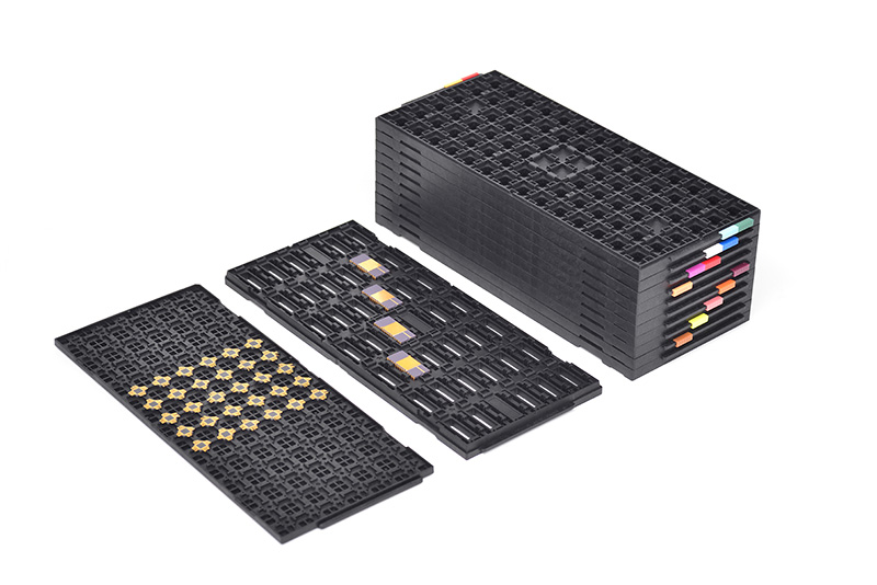
The most common formats are the 2-inch (136mm x 315mm) and 4-inch (279mm x 341mm) trays. The 4-inch tray, often referred to as a "JEDEC matrix tray," is the workhorse for volume manufacturing. The PDF specifies:
Length and Width: Typically 322.6mm x 135.9mm for the standard "2-inch" tray (the name refers to the rail spacing, not the overall dimension). Tolerances are usually ±0.25mm.
Overall Height (Stacking Clearance): The total height of the tray, including the feet, which allows for secure stacking without the components touching the tray above. This is critical for automated magazine loaders.
Corner Cutouts: Polarization features, often a cut corner or notch, ensure that trays are loaded into equipment in the correct orientation.
Pocket Geometry: The Heart of Component Protection
The pocket design is where precision is paramount. The JEDEC tray dimensions PDF provides detailed cross-sections for each package type (e.g., a 7x7mm BGA versus a 10x10mm QFN). Critical parameters include:
Pocket Width, Length, and Depth: These are designed to provide a snug fit without stressing the package body. For fine-pitch devices, the clearance may be as little as 0.1mm per side.
Chamfer and Radius Details: Lead-in chamfers at the pocket opening guide the component into place during the pick-and-place operation and prevent stubbing.
Stand-off Features: Small raised features within the pocket that lift the component slightly, preventing the package body or solder balls from sticking to the tray surface via adhesion or vacuum.
Material Science and Dimensional Stability
A JEDEC tray dimensions PDF defines the final geometry, but the choice of material determines whether those dimensions hold true under real-world conditions. The semiconductor industry has moved decisively toward high-performance polymers.
PES and PEI: The Industry Standards
Polyethersulfone (PES) and Polyetherimide (PEI) are the materials of choice for high-temperature trays. They offer:
High Glass Transition Temperature (Tg): PES and PEI have Tg values exceeding 200°C, allowing them to withstand baking processes (up to 150°C or more) without warping or softening.
Inherent ESD Protection: Unlike coated surfaces, these materials are compounded with permanent anti-static agents, ensuring consistent surface resistivity over the life of the tray.
Low Moisture Absorption: Critical for maintaining dimensional stability. High moisture absorption can cause the polymer to swell, altering pocket dimensions and leading to handling issues.
The Impact of Thermal Cycling on Tray Geometry
One of the hidden challenges not explicitly detailed in the JEDEC tray dimensions PDF is the effect of thermal expansion. Trays used in burn-in or subjected to temperature cycling must have a Coefficient of Thermal Expansion (CTE) that is compatible with both the IC package and the handling equipment. A mismatch can cause the component to shift within the pocket or, in extreme cases, crack the package. Advanced tray manufacturers, including Hiner-pack, perform finite element analysis (FEA) to optimize pocket design for thermal stability, ensuring that the dimensions remain within spec from -40°C to +150°C.
Common Pitfalls When Interpreting JEDEC Tray Drawings
Even with a reliable JEDEC tray dimensions PDF, misinterpretation is a frequent source of costly errors. Here are three critical areas of confusion:
Overlooking Tolerances and Stack-Up
The PDF provides tolerances for individual features, but the real-world performance depends on the stack-up of these tolerances. For example, a pocket that is at its maximum allowable width combined with a component at its minimum width might result in excessive movement during shipping, causing "die bounce" or lead damage. Conversely, a tight stack-up can cause insertion issues. It is essential to consider statistical tolerance analysis, not just nominal values.
Assuming "One Size Fits All" for Similar Packages
A 14x14mm BGA from one manufacturer may have a slightly different package thickness or ball array than a 14x14mm BGA from another. The JEDEC tray dimensions PDF provides a standardized envelope, but it is always advisable to validate the tray with the specific component, especially for high-volume production runs. Hiner-pack offers custom modifications to standard trays to accommodate subtle variations while maintaining full JEDEC compliance for the outer dimensions.
Material Selection for High-Temperature Processes
Using a standard conductive polystyrene tray in a high-temperature bake application is a recipe for disaster. Polystyrene softens around 80-90°C, causing the tray to warp and potentially damaging the ICs. Always cross-reference the material properties listed in the JEDEC tray dimensions PDF (or the associated material data sheet) with the actual process temperature profile.
The Role of JEDEC Trays in Automated Assembly Lines
In a modern SMT line, speed and accuracy are everything. High-speed pick-and-place machines, such as those from ASMPT or Fuji, rely on the precise registration of the tray in the feeder. The JEDEC tray dimensions PDF ensures that the tray's locating features—such as alignment holes and edge rails—match exactly with the feeder's tooling pins. Any deviation can lead to missed picks, reducing overall equipment effectiveness (OEE) and potentially damaging the placement nozzles.
Hiner-pack: Engineering Precision Beyond the PDF
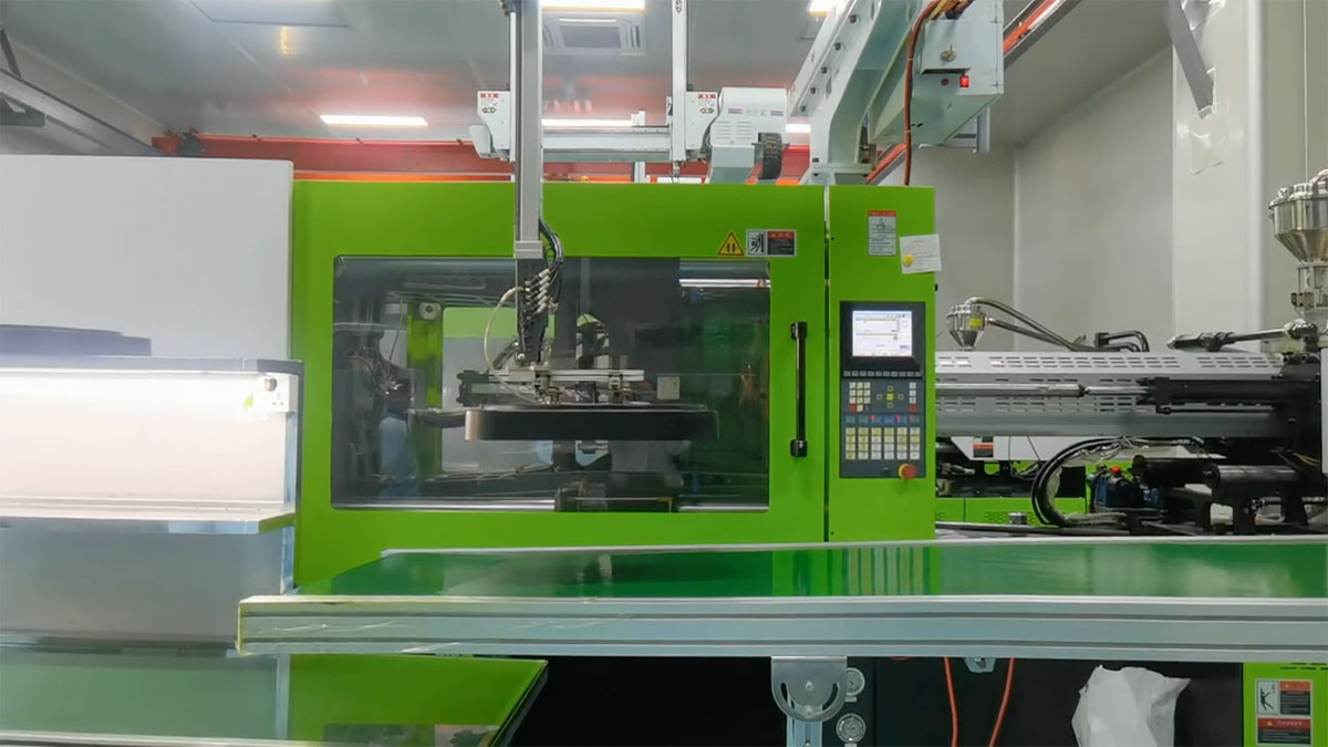
While the JEDEC tray dimensions PDF provides the blueprint, transforming that blueprint into a reliable, durable, and clean product requires deep manufacturing expertise. Hiner-pack has established itself as a trusted partner by going beyond the minimum requirements. Their injection molding processes are carried out in ISO Class 7 cleanrooms, and every tray is 100% visually inspected for flash, contamination, and dimensional accuracy using automated optical systems. By integrating high-purity PES and PEI resins with precision tooling, Hiner-pack ensures that their trays deliver consistent performance, lot after lot, meeting the demands of the most stringent automotive and industrial applications.
Future Trends: The Evolution of JEDEC Tray Standards
As IC packages continue to shrink and become more complex (e.g., fan-out wafer-level packaging, chiplets), the demands on tray technology are increasing. Future revisions to the JEDEC tray dimensions PDF may need to address:
Thinner Packages: Requiring even more precise pocket depth control to prevent "flying" components.
Larger Panel-Level Packaging: Driving demand for larger tray formats with extremely flat surfaces.
Enhanced Cleanliness: Stringent requirements for low outgassing and low particle generation, especially for sensitive MEMS and optical devices.
Digital Integration: Trays with embedded RFID for smart tracking and traceability throughout the supply chain.
Staying ahead of these trends requires close collaboration between IC assemblers, equipment manufacturers, and tray suppliers. Accessing the latest version of the JEDEC tray dimensions PDF and understanding its nuances is the first step toward mastering this critical aspect of semiconductor logistics.
Frequently Asked Questions (FAQ)
Q1: Where can I download the official JEDEC tray dimensions PDF for
free?
A1: The official, most up-to-date JEDEC standards, including
JEP95, are typically available for purchase from the JEDEC website (jedec.org).
However, many tray manufacturers, including Hiner-pack, provide detailed dimensional
drawings and specification sheets on their product pages that are derived from
these standards and sufficient for most engineering and procurement
purposes.
Q2: What is the difference between a "matrix tray" and a "JEDEC
tray"?
A2: The terms are often used interchangeably, but
technically, a matrix tray is a type of JEDEC tray. "Matrix tray" refers to the
grid-like arrangement of pockets. The JEDEC tray dimensions
PDF defines the specifications for these matrix trays, ensuring they conform
to the standard outer dimensions and interface features required for automated
handling.
Q3: How do I verify if a specific tray is truly compliant with JEDEC
dimensions?
A3: Compliance verification requires precision
measurement tools. Use an optical comparator or a coordinate measuring machine
(CMM) to check critical dimensions: overall length/width, height, pocket size,
and corner radii. Compare these measurements against the tolerances provided in
the relevant JEDEC tray dimensions PDF. Also, verify the material's ESD
properties with a surface resistance meter.
Q4: Can I use a JEDEC tray designed for QFPs to hold
BGAs?
A4: Generally, no. QFP pockets are designed to accommodate
gull-wing leads on the sides, while BGA pockets are designed to protect solder
balls on the bottom. Using the wrong tray can damage the leads or balls. Always
consult the JEDEC tray dimensions
PDF that corresponds to the specific package type (e.g., MO-220 for BGA,
MO-136 for QFP).
Q5: What does "dry pack" mean in relation to JEDEC
trays?
A5: "Dry pack" refers to the process of baking
moisture-sensitive devices (MSL components) and then sealing them in a
moisture-barrier bag with desiccant, often while still in their JEDEC trays. The
trays themselves must be capable of withstanding the baking temperature
(typically 125°C for 24-48 hours) without warping, which is why high-temperature
materials like PES are essential.
Q6: How often should JEDEC trays be cleaned, and what is the best
method?
A6: Cleaning frequency depends on the fab environment and
the sensitivity of the devices. For particle-sensitive applications, trays may
be cleaned before each use. The recommended method is ultrasonic cleaning or
washing with deionized water and a mild, non-ionic surfactant, followed by a
thorough rinse and drying in a HEPA-filtered oven. Always ensure the cleaning
agent is compatible with the tray material.
Q7: Are there JEDEC standards for tray reusability or
lifetime?
A7: JEDEC does not explicitly define a tray lifetime. The
usable life depends on wear and tear, accumulation of contamination, and loss of
ESD properties. Trays should be inspected regularly for cracks, warpage, and
surface damage. If a tray no longer holds components securely or causes feeding
issues in an SMT line, it should be retired, even if its nominal dimensions
still appear correct.