For semiconductor backend facilities (assembly, test, and packaging), the tray jedec is not merely a shipping container—it is a precision fixturing tool that directly impacts final test yield, device coplanarity, and automated handling efficiency. JEDEC tray standards (primarily JESD75 series) define cavity dimensions, stackability, and material class for integrated circuits (ICs) in various package types (QFP, BGA, QFN, SOP). However, procurement engineers often face hidden challenges: tray warpage after repeated thermal cycling, inconsistent surface resistivity, and incompatibility with pick-and-place nozzle systems. This article provides a data-driven examination of tray jedec engineering, covering material selection, cleanliness protocols, and validation methods. Hiner-pack offers a full range of compliant trays for 2” to 300mm wafer and IC carriers, referenced throughout this guide.
1. Dimensional Conformance to JEDEC Publication 95 (JESD75)
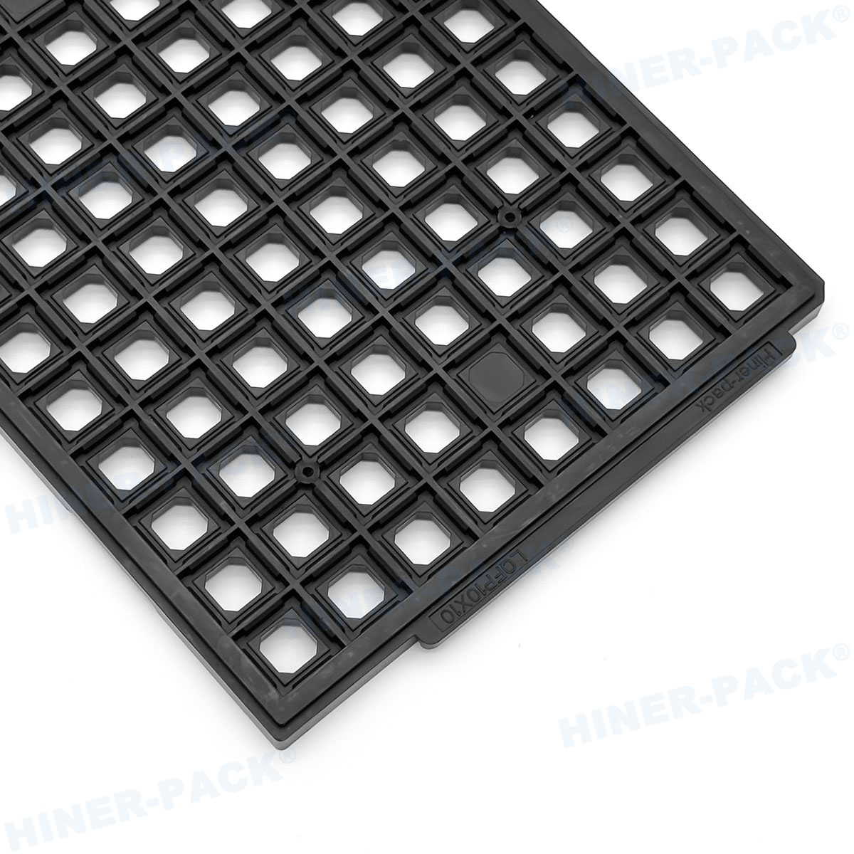
Any compliant tray jedec must adhere to matrix dimensions and cavity pitch specified in JESD75-1 through JESD75-4. Key parameters include:
Overall tray size: Standard outline 322mm x 135mm (for 12” wafer boxes) or 160mm x 320mm for smaller IC trays. Thickness ranges from 7mm to 12mm depending on package height.
Cavity array: Common matrices are 5×12, 6×15, or 8×18. Cavity pitch tolerance ±0.05mm to align with vacuum pickup tips.
Corner chamfers and orientation marks: JEDEC mandates a specific notch geometry to prevent mis-orientation during automated loading (SEMI G84-0306).
Non-conforming trays cause nozzle misses or component skew during placement. For high-speed assembly (up to 25k UPH), a 0.1mm positional error leads to 0.5% pick-up failure. Therefore, request a First Article Inspection (FAI) report with Cpk ≥1.33 for all critical dimensions. Hiner-pack's product line includes JEDEC trays with laser-scanned cavity coordinates.
2. Material Science: Static-Dissipative vs. Conductive Trays
JEDEC trays are classified into three material categories per ANSI/ESD S541:
Low charging (static-dissipative): Surface resistivity 10⁶ – 10⁹ Ω/sq, typically carbon-filled polycarbonate (PC) or ABS. Used for most IC storage (MSL 2/3).
Conductive: Resistivity <10⁵ Ω/sq, often carbon-fiber reinforced PEEK or PEI. Required for highly sensitive devices (RF, GaAs) with ESD withstand voltage <250V.
Insulative (avoided): >10¹² Ω/sq – pure polypropylene or PET. Not suitable for IC handling due to charge accumulation.
The selection impacts three areas: charge decay time (less than 2 seconds from 1000V to 100V per ESD STM11.11), particle attraction, and outgassing. For tray jedec used in vacuum sealing (with MBB bags), low-outgassing materials (TML <0.5% per ASTM E595) prevent corrosion of bond pads. Many engineers overlook that carbon fillers can shed conductive particles; thus, a “clean carbon” formulation is preferred.
When comparing tray jedec options against waffle packs or gel boxes, consider thermal range: standard JEDEC trays operate from -40°C to +125°C, while high-temperature versions (for solder reflow handling) withstand 260°C peak for 30 seconds.
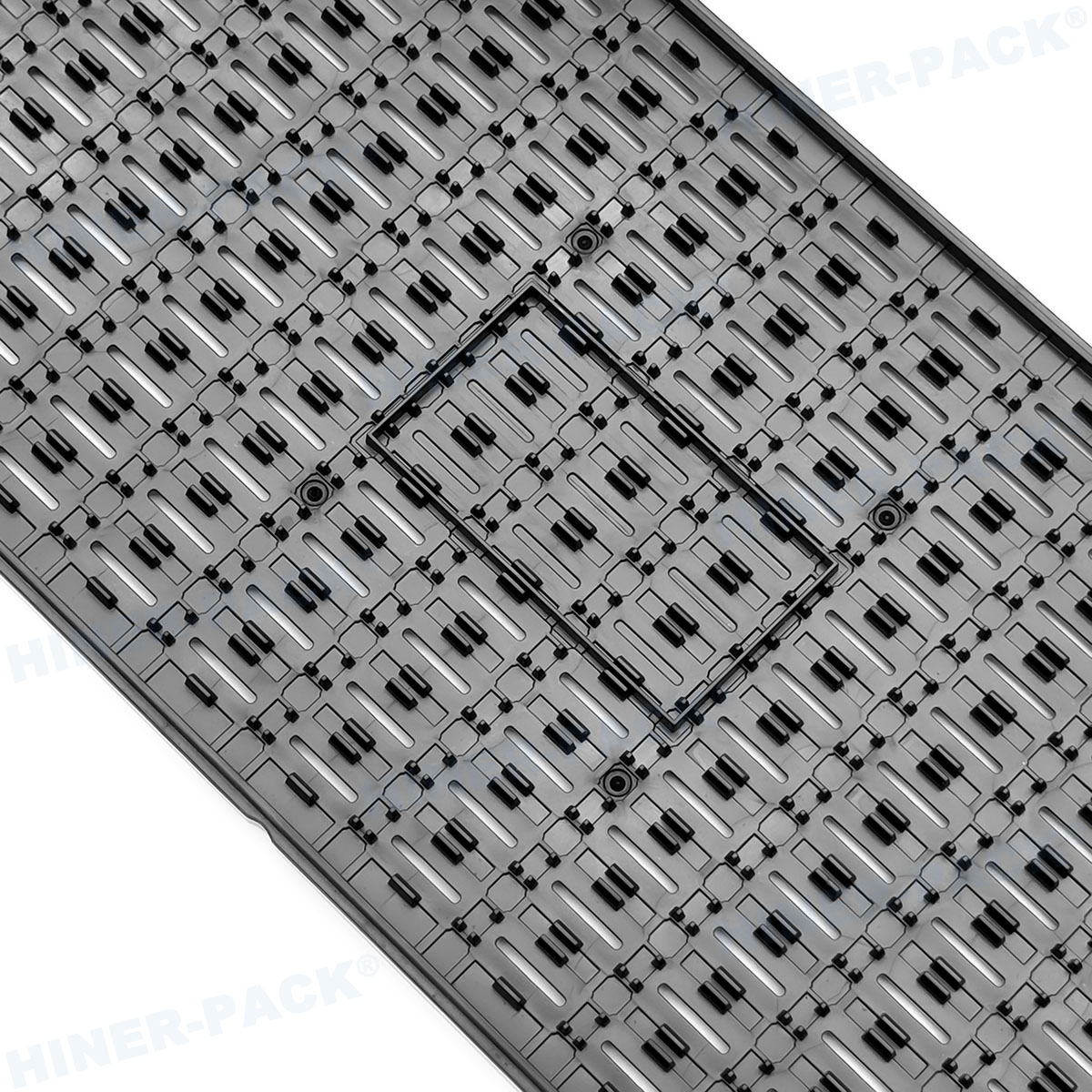
3. Warpage Control and Flatness Specifications
One of the most frequent complaints from assembly lines is tray warpage causing IC tilt or misalignment. JEDEC standard JESD75-2 specifies maximum bow and twist: ≤0.5mm per 100mm length for empty trays, and ≤0.8mm for fully loaded trays after three reflow cycles. Warpage arises from:
Mold shrinkage mismatch: Between resin and carbon filler.
Moisture absorption: Polycarbonate can absorb 0.15% moisture, leading to 0.1-0.3% expansion.
Improper annealing: Post-mold stress relief (4 hours at 120°C) is mandatory for dimensionally stable trays.
To validate warpage, use a granite surface plate and feeler gauge. For high-volume procurement, demand a shadow moiré measurement report. A quality tray jedec supplier, like Hiner-pack, provides a 2D flatness map for each cavity matrix.
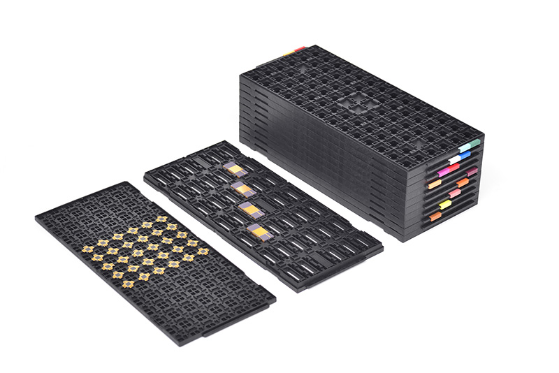
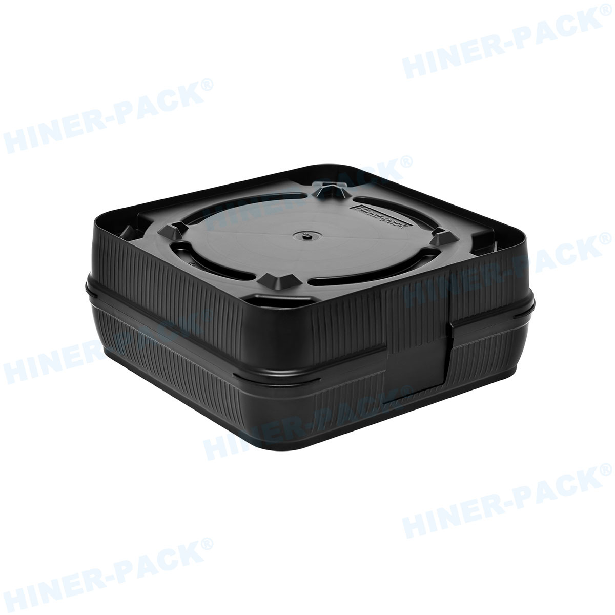
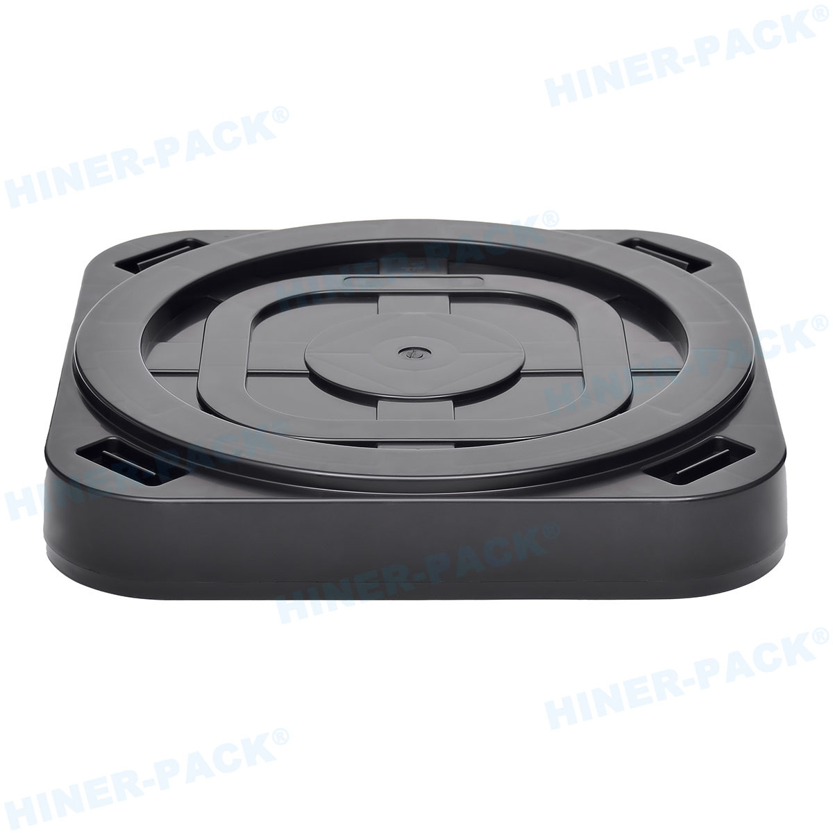
4. Stackability and Nesting Design for Automated Magazines
In backend fabs, JEDEC trays are stacked inside magazines (e.g., JEDEC 12” magazine or inline feeders). The stacking feature consists of stacking ribs on the tray bottom and recesses on the top cover. Key parameters:
Stacking pitch: Height from top of IC to bottom of upper tray – typically 1-2mm clearance above device.
Anti-slide texture: Micro-ribs to prevent tray shifting during vibration (ISTA 2A test).
Alignment pins: Some trays include corner holes for magazine guidance.
Poor stackability leads to IC-to-upper-tray contact, causing lead bending or solder ball damage. For BGA devices with ball diameter 0.3mm, even 0.2mm contact pressure can deform solder balls. Therefore, request a stack height gauge test with 10 loaded trays.
Furthermore, Hiner-pack's JEDEC trays are designed for both manual and automatic magazine loading, with beveled edges to reduce friction.
5. Cleanroom Compatibility and Particle Shedding Limits
For Class 1 to Class 1000 cleanrooms (ISO 3-6), a tray jedec must meet SEMI E49.5 guidelines for extractable ions and particles. Typical specifications:
Particle generation: <50 particles >0.3µm per tray after 60 sec vibration (SEMI E46).
Ionic contamination: Chloride, fluoride, sodium each <0.02 µg/cm² after 72-hour DI water extraction.
Metallic residues: Fe, Cr, Ni, Cu <0.01 µg/cm² (ICP-MS method).
Standard injection-molded trays often have mold release agents (zinc stearate) that contaminate devices. Post-mold cleaning with CO₂ snow or deionized water rinse is required. For mission-critical applications (MEMS, optical sensors), specify “ultra-clean JEDEC trays” with double-bagging and lot-level certification.
6. Thermal and Chemical Resistance for MSL Handling
ICs are classified by Moisture Sensitivity Level (MSL 1 to 6). JEDEC trays used for MSL 3 or higher often require baking at 125°C for 24 hours before dry packing. Material limitations:
PC-based trays: Max continuous use 120°C – suitable for baking but not for reflow.
PEI (Ultem) trays: Withstand 170°C continuous, 200°C intermittent – used for lead-free soldering processes.
PEEK trays: Up to 260°C, but high cost (3-5x PC).
Also, chemical resistance to flux solvents (IPA, acetone, mild acids) is necessary for trays that go through cleaning cycles. PC trays craze in acetone; PEI and PEEK have excellent resistance. Specify chemical compatibility if trays are reused in soldering areas.
When selecting a tray jedec for high-temperature applications, Hiner-pack offers PEI and carbon-fiber PEEK variants with thermal stability data.
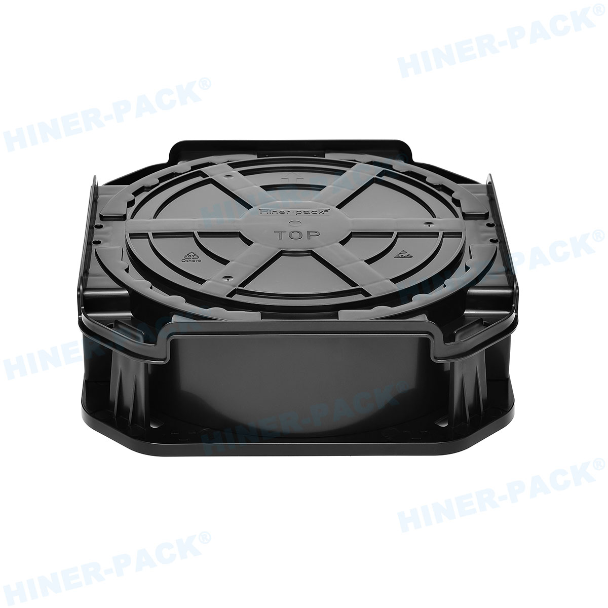
7. Automation Interfaces: Vision Systems and Pick-and-Place
Modern SMT lines use vision-guided nozzles. A tray jedec must provide:
Contrast marks: Fiducial spots for camera alignment (typically 2mm diameter white-on-black).
Open cavity walls: Angled sidewalls (15-20 degrees) to allow nozzle access without collision.
Non-glare finish: Matte texture to prevent specular reflection.
Poorly designed trays increase “component not found” errors, reducing throughput. For matrix trays with 300+ cavities, cycle time increases by 0.2 seconds per retry. Over a 24-hour run, this adds 1.5 hours of lost production. Therefore, request a “vision report” from the tray supplier, confirming that every cavity is recognized by common placement systems (Fuji, Siemens, Panasonic).
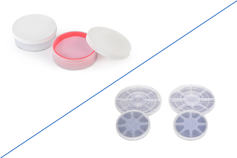
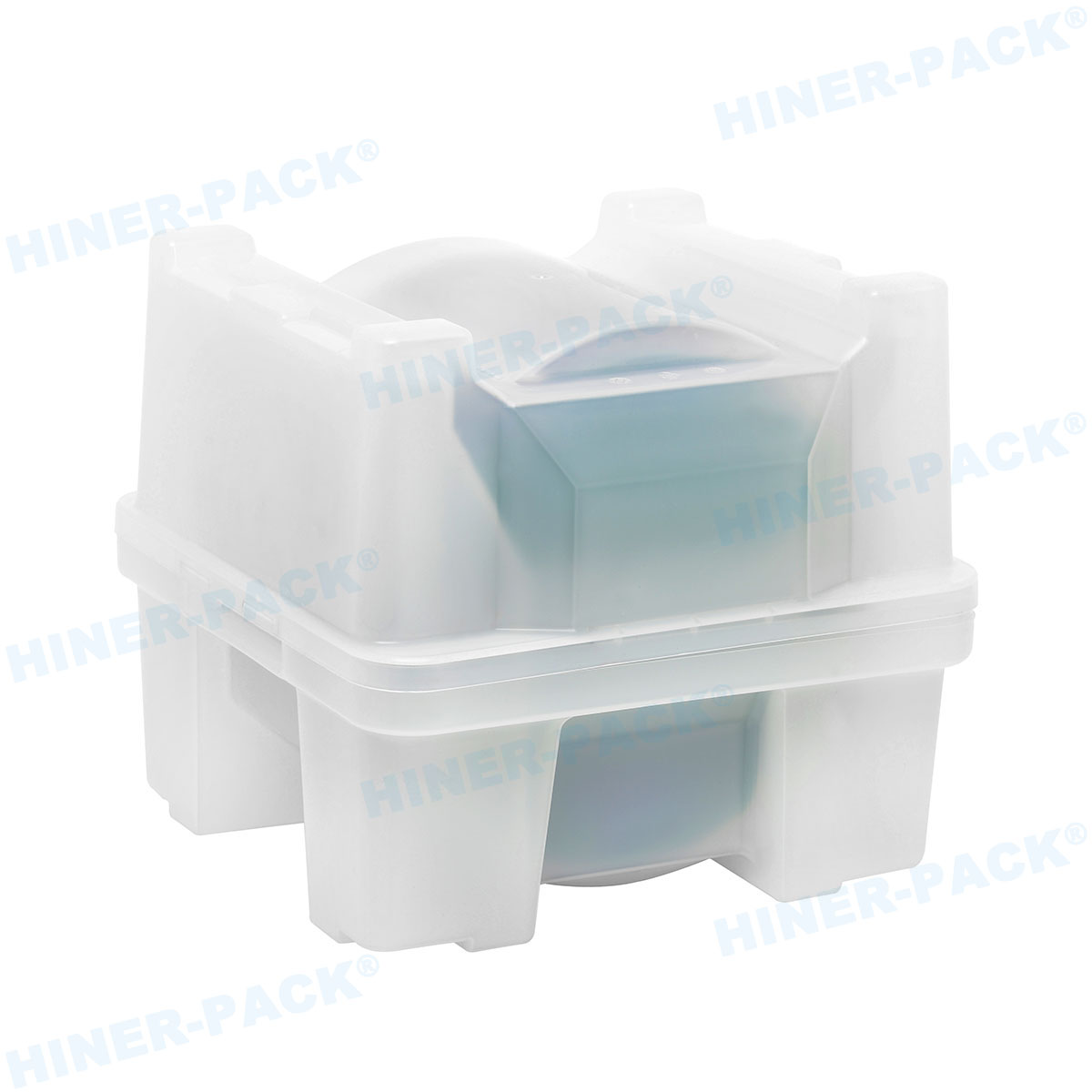
8. Comparison with Alternative Carriers: Waffle Packs and Gel Boxes
Engineers often ask: when to use a JEDEC tray versus a waffle pack or gel box? The table below guides selection:
| Parameter                     | JEDEC Tray                          | Waffle Pack (Chip Tray)            | Gel Box                              |
|-------------------------------|-------------------------------------|--------------------------------------|--------------------------------------|
| Typical device type           | Singulated ICs (BGA, QFP, QFN)      | Bare die or small chips              | Thin wafers or fragile dice          |
| Device orientation            | Cavity-defined (pockets)            | Waffle pattern grid                  | Embedded in gel matrix               |
| Stackability                  | Yes (with ribs)                     | Limited (single or low stack)        | Yes (rigid shell)                    |
| ESD protection                | Dissipative/conductive plastic      | Dissipative plastic or coated        | Dissipative gel + conductive box     |
| Cleanliness (particles)       | Good (with cleaning)                | Good                                 | Excellent (low shedding)             |
| Cost per device               | Low (reusable 20-50 cycles)         | Low to medium (often single-use)     | High (but reusable 100+ cycles)      |
For high-volume IC shipping (e.g., 100k units per week), the tray jedec remains the most cost-effective and automation-friendly solution. Waffle packs are preferred for small-quantity die sales, while gel boxes protect ultra-thin wafers during inter-facility transport.
Frequently Asked Questions (FAQ) about JEDEC Trays
Q1: What are the standard JEDEC tray sizes for 12” wafer
processing?
A1: JEDEC does not directly specify wafer tray sizes;
however, for IC trays used after wafer sawing, the common footprint is 322mm x
135mm (compatible with 12” wafer frame dimensions). For back-end automation,
trays follow JESD75-3 (matrix trays for automated handling). Always confirm the
exact outline with your equipment supplier.
Q2: Can I clean and reuse a JEDEC tray multiple times? What cleaning
method is safe?
A2: Yes, most static-dissipative trays can be reused
20-50 cycles. Recommended cleaning: ultrasonication in DI water (40°C) with mild
detergent (1% Deconex), followed by DI rinse and nitrogen dry. Avoid strong
alkaline solutions or ketones (acetone, MEK) as they degrade polycarbonate and
carbon fillers. After cleaning, re-verify surface resistivity (10⁶–10⁹
Ω/sq).
Q3: How do I verify that a tray meets JEDEC standards without
expensive equipment?
A3: At a minimum, perform three checks: (1)
Measure cavity pitch using a calibrated caliper – should be within ±0.05mm of
drawing; (2) Place tray on a flat surface and measure gap under corners with
feeler gauge – warpage should be <0.5mm; (3) Use a surface resistivity meter
(e.g., ACL 800) on at least five cavities. If any fails, request a full report
from supplier. Hiner-pack provides free
sample verification kits for qualified buyers.
Q4: What is the difference between “JEDEC tray” and “IC
tray”?
A4: The terms are often used interchangeably. However, “JEDEC
tray” strictly refers to trays designed per JEDEC publication JESD75
(dimensional standards). “IC tray” is a broader term that may include
non-standard custom cavities. For procurement, always specify “JEDEC-compliant
tray” to ensure interoperability with magazine feeders and tape-and-reel
machines.
Q5: Do JEDEC trays have a shelf life? How to store
them?
A5: Trays themselves do not expire, but static-dissipative
properties can degrade over 5-7 years due to oxidation of carbon filler or
humidity. Store trays in anti-static bags, away from UV light and high
temperature (>40°C). Before using aged trays (>2 years), measure
resistivity and clean with isopropyl alcohol (IPA) to remove surface
contamination. For MSL-sensitive devices, bake trays at 125°C for 4 hours before
loading ICs.
Conclusion and Procurement Guidance
The tray jedec is a foundational tool for semiconductor backend logistics, directly affecting pick-and-place yield, ESD safety, and thermal processing compatibility. Key takeaways for engineering buyers:
Demand JESD75 dimensional conformance with FAI and Cpk data.
Select material (dissipative vs. conductive) based on device ESD sensitivity and temperature requirements.
Validate warpage (<0.5mm/100mm) and stackability (10-tray column test).
Require cleanliness certification (SEMI E49.5) for Class 1000 or higher cleanrooms.
Hiner-pack offers a complete portfolio of JEDEC trays, waffle packs, and gel boxes, all supplied with full documentation: material certificates, warpage maps, and ESD test reports. Their engineering team can customize cavity patterns for non-standard package sizes (e.g., 15x15mm QFN with exposed pad).
Request a technical consultation or sample evaluation: Visit Hiner-pack’s JEDEC tray page to download specifications, request a quote, or arrange a 30-minute webinar on tray qualification methods. For volume orders (10,000+ trays), they provide free first article and three-month warpage monitoring. Send your inquiry now to improve your IC handling yield.
Inquiry contact: Hiner-pack – https://www.waferboxes.com/ | Email: sales@waferboxes.com | Phone: +86 755 2322 9236. All inquiries receive a technical response within 24 hours.