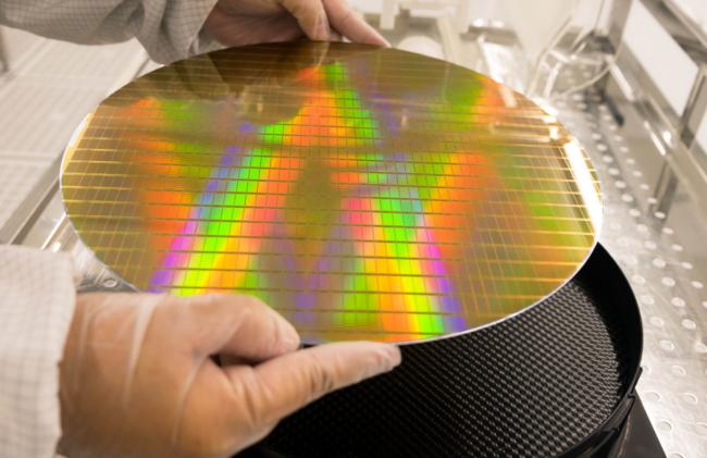
In a modern semiconductor fab, silence reigns. The hum of machinery is constant, but human presence is minimal. The real work is done by a symphony of automated systems, robots, and precision handling equipment. At the critical junctions of this automation, where wafers are transferred, queued, and presented to tools, you'll find a deceptively simple component: the LC tray.
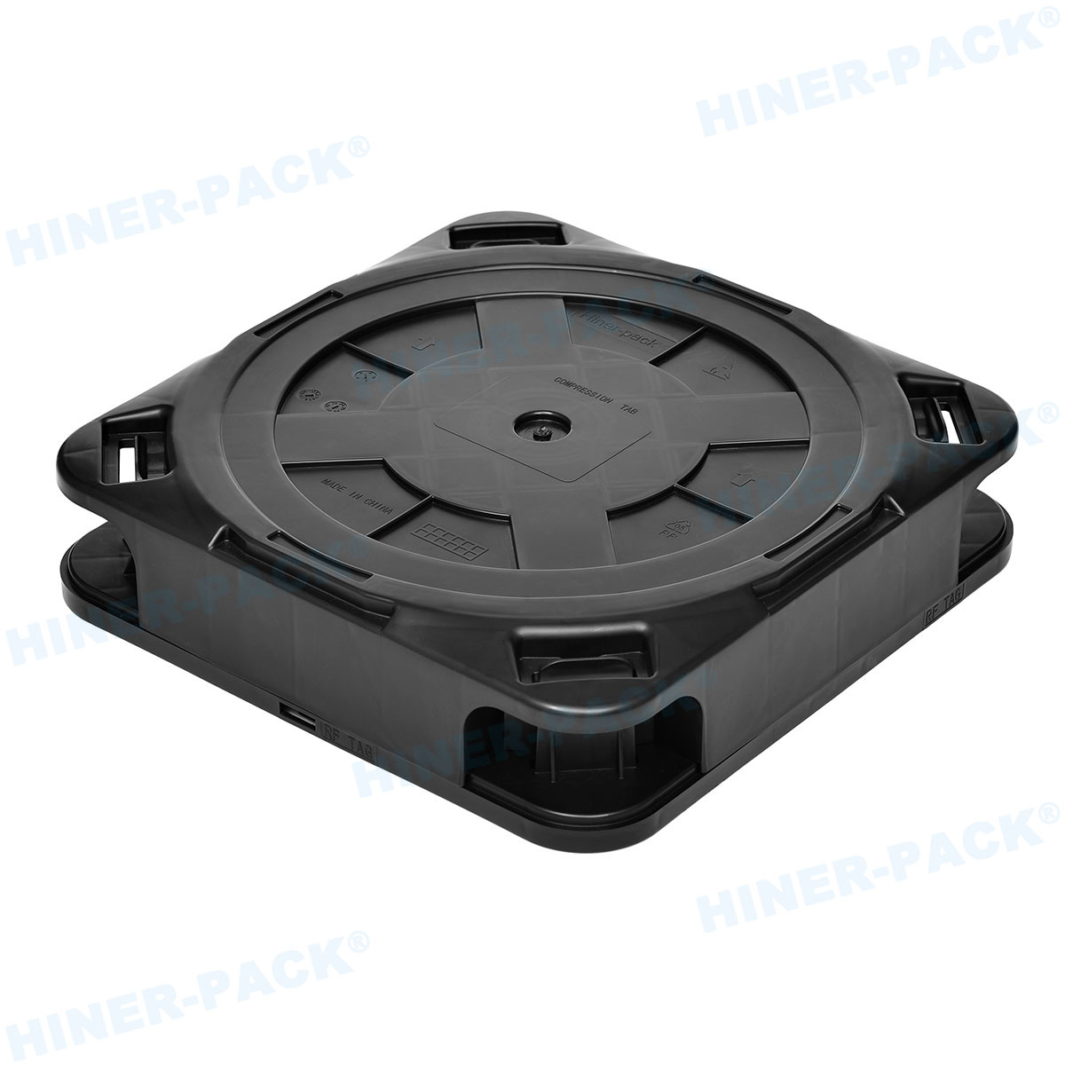
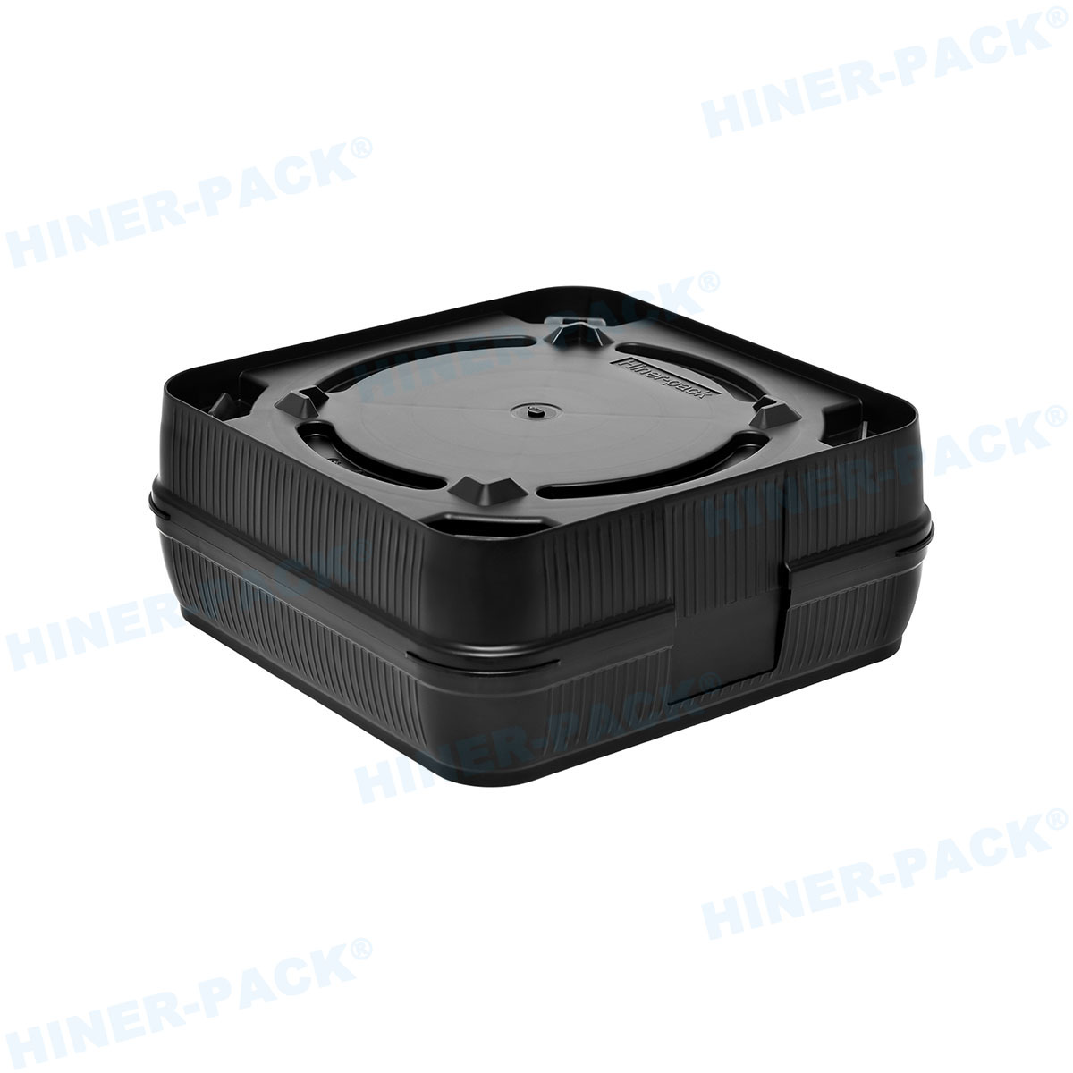
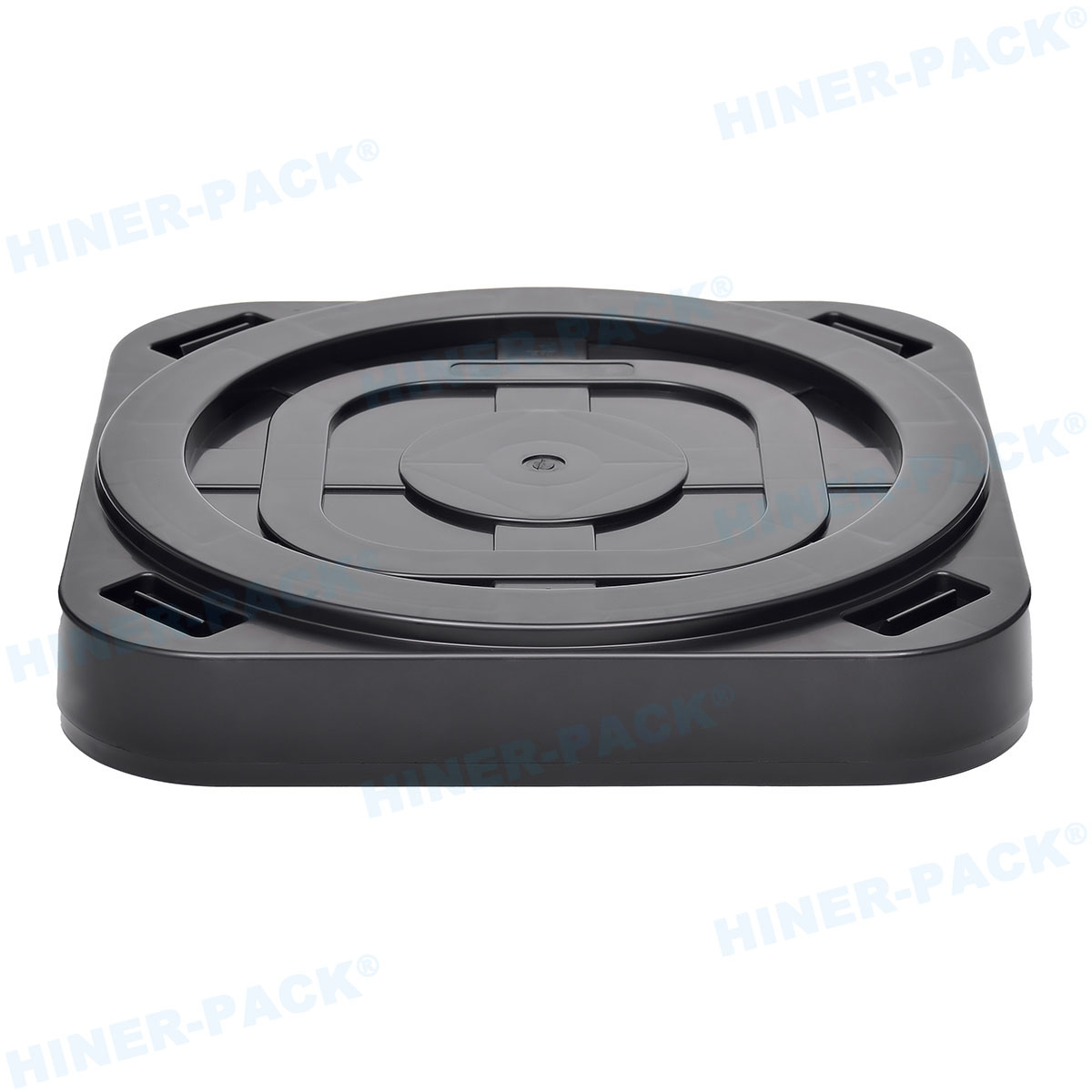
Short for Load Port Tray or sometimes referred to in context as a Lithography Carrier Tray, an LC tray is a standardized platform. Its job is to hold and position Front-Opening Unified Pods (FOUPs) or other wafer carriers at the load port of processing equipment. It is the essential physical interface between the fab's material handling system and the multi-million dollar tool that will perform the next fabrication step.
Think of it as the precise docking station for valuable wafer cargo. Without a reliable, perfectly flat, and mechanically robust LC tray, the dance of automation stumbles. Misalignment, vibration, or instability at this point can lead to handling errors, wafer damage, and costly tool downtime. Companies like Hiner-pack specialize in engineering these critical interfaces to exacting standards.
The Role of the LC Tray in the Material Flow
The semiconductor process flow involves hundreds of steps. Wafers move from etchers to deposition tools, to lithography scanners, and to metrology stations. This movement is managed by an Automated Material Handling System (AMHS) – overhead hoists, rail-guided vehicles, or conveyor systems.
The LC tray is the destination point. An AMHS vehicle delivers a FOUP containing 25 wafers to a tool's load port. It precisely places the FOUP onto the awaiting LC tray. Once seated, the tray may index or align the carrier. Then, the tool's load port door opens, a robotic arm extracts the wafers from the FOUP, and feeds them into the process chamber.
This handoff happens thousands of times a day. The LC tray must ensure this transfer is flawless every single time.
Critical Design and Performance Factors
Not all LC trays are created equal. Their design is governed by a balance of rigidity, precision, and compatibility.
Flatness and Stability
This is non-negotiable. The seating surface of an LC tray must have exceptional global and local flatness. Any warp or bow will be transmitted to the FOUP. This can cause misalignment with the tool's kinematic pins – the locating features that ensure absolute positional accuracy. Poor seating leads to robotic handling faults, aborted cycles, and potential wafer scrap.
Mechanical Rigidity and Load Capacity
An LC tray is a structural component. It must support the significant weight of a fully loaded 300mm FOUP (which can exceed 8 kg) without flexing. This rigidity must be maintained across thousands of cycles and years of service. Materials like high-grade aluminum alloys, often with precision machining and strategic ribbing, are common. Hiner-pack utilizes advanced engineering designs to maximize strength-to-weight ratio, ensuring long-term performance under constant load.
Compatibility and Standardization
The dimensions, locator pin positions, and mounting features of an LC tray must strictly adhere to industry standards. SEMI standards, particularly those defining 300mm load port interfaces (like SEMI E15.1 and related bulletins), dictate these specifications. A tray must be compatible with both the AMHS delivery system and the specific make/model of the process tool's load port. This plug-and-play interoperability is vital for fab flexibility.
Surface Properties and Cleanliness
In a cleanroom, particle generation is the enemy. The LC tray surface must be smooth, hard, and resistant to wear. Anodized aluminum coatings are typical, providing a hard, particle-shedding surface. Some designs incorporate static-dissipative properties to prevent charge buildup that could attract airborne contaminants.
Vibration Damping
High-speed automation induces vibration. A well-designed LC tray may integrate damping elements or a tuned mass to absorb and minimize harmonic vibrations. This prevents the vibration from affecting the delicate wafers inside the FOUP or causing alignment issues during the critical seconds of carrier docking.
Integration with Advanced Fab Systems
The humble LC tray is getting smarter. As fabs move towards Industry 4.0 and greater data integration, the tray can be part of a larger monitoring ecosystem.
RFID Integration
Trays can be equipped with RFID tags. This allows the tool and AMHS to identify not just the FOUP, but the specific tray it is on. This aids in tracking, maintenance scheduling, and verifying tool-tray compatibility.
Sensor Readiness
Advanced trays may be designed to accommodate embedded sensors. These could monitor parameters like tray temperature (critical for some processes), vibration levels during transport, or even confirm the presence and proper seating of the FOUP through micro-switches or optical sensors.
The Impact on Overall Equipment Effectiveness (OEE)
Tool availability is a key metric in fab productivity. A failed handoff at the load port causes a tool interruption. If an LC tray is worn, warped, or damaged, it becomes a recurring source of these interruptions.
Investing in high-quality, durable LC trays from a trusted supplier is a proactive maintenance strategy. It reduces mean time to recover (MTTR) from handling faults, extends the life of the more expensive load port hardware, and contributes directly to higher tool OEE. The precision engineering in a Hiner-pack LC tray, for example, is a direct investment in predictable, uninterrupted production.
Selection and Maintenance Best Practices
Selecting an LC tray involves more than just checking a part number. Consider the tool manufacturer's specifications, the expected duty cycle, and the compatibility with your AMHS. Look for suppliers with a deep understanding of semiconductor material handling dynamics.
Maintenance is straightforward but critical. Trays should be included in regular cleanroom cleaning protocols. Their seating surfaces and locator features must be inspected periodically for wear, scratches, or particle buildup. A simple periodic check with a precision straightedge can reveal issues before they cause a downtime event.
The Foundation of a Reliable Handoff
In the quest for smaller nodes and higher yields, engineers focus on lithography, etching, and materials science. However, the physical infrastructure that enables these processes is equally important. The LC tray is a foundational element of that infrastructure.
It is the quiet, reliable workhorse that ensures multi-million dollar tools can consistently access the wafers they need to process. By guaranteeing a perfect, stable, and repeatable interface, a precision LC tray removes a significant variable from the manufacturing equation. It allows process engineers to focus on the chemistry and physics inside the tool, confident that the wafers will arrive and depart without incident.
For fabs looking to maximize uptime and protect their wafer-in-process, specifying and maintaining high-performance LC trays is a simple, cost-effective strategy. Partners like Hiner-pack provide the engineering rigor and semiconductor-grade quality required for this critical role.
Frequently Asked Questions (FAQs)
Q1: What does "LC" stand for in LC tray?
A1: In the semiconductor context, "LC" most commonly stands for "Load Port Tray" or "Load/Unload Tray." It is the tray mounted on the standardized load port of process equipment where a wafer carrier (like a FOUP) is placed by the AMHS for tool access.
Q2: How often should LC trays be inspected and cleaned?
A2: Inspection frequency depends on usage. High-throughput ports may need a visual and functional check weekly. Cleaning should align with your fab's preventative maintenance schedule, often during regular tool PMs. The critical seating surface should be wiped clean with approved cleanroom wipes and solvent to remove any potential particles or films.
Q3: Can a warped or damaged LC tray actually break wafers?
A3: Indirectly, yes. A warped LC tray causes misalignment between the carrier and the tool's robotic handler. This can lead to the robot arm colliding with the carrier or wafers inside, or cause wafers to be dropped or scraped during transfer. It is a primary cause of handling-related wafer breakage and scrap.
Q4: Are LC trays interchangeable between different tool brands?
A4: Not automatically. While they follow SEMI standards for the carrier interface, the mounting hardware to the load port itself can be tool-specific. Always verify the exact mechanical drawings and part numbers specified by the tool manufacturer (OEM) or a qualified third-party supplier like Hiner-pack that guarantees compatibility.
Q5: What are the signs that an LC tray needs to be replaced?
A5: Key signs include: an increase in load port alignment errors or "handoff fail" alarms on the tool, visible wear or scratches on the kinematic pin holes or carrier seating surface, measurable flatness deviation beyond specification, or physical damage from an impact. Proactive replacement based on service life is better than waiting for a failure.