Radio Frequency Integrated Circuits (RFICs) operate at gigahertz frequencies,
where signal integrity, thermal management, and contamination control directly
influence device yield. The physical carrier used during testing, baking, and
surface-mount assembly—the RFIC
JEDEC matrix IC trays—must satisfy rigorous mechanical, electrical,
and thermal parameters. This guide examines JEDEC tray specifications, material
science trade-offs, and integration strategies for automated semiconductor
lines. For engineers specifying carriers for RF front-end modules or mmWave
chipsets, these technical details define reliability.
1. Why Standard RFIC Handling Demands JEDEC Matrix Trays
RFICs present four distinct challenges that generic anti-static trays cannot
address: extreme coplanarity requirements for high-pin-count packages, moisture
sensitivity level (MSL) compliance, low outgassing for cavity packages, and
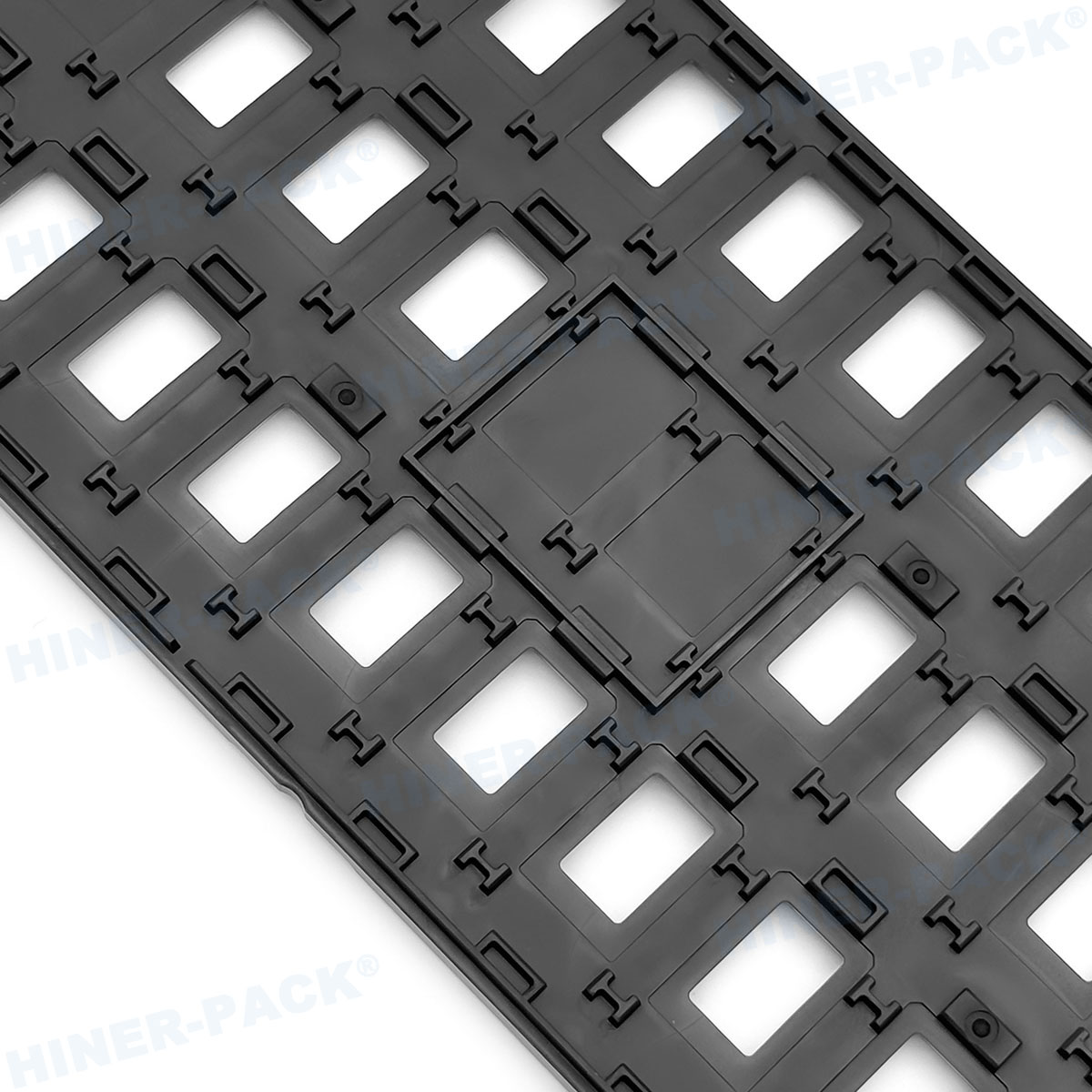
compatibility with tape-and-reel or direct pick-and-place. JEDEC matrix
trays—manufactured under JESD51 and J-STD-033 frameworks—provide precision pocket geometries that secure devices without edge
stress. The matrix format (rows and columns) allows dense storage while
maintaining alignment for automated handlers.
Coplanarity control: RFIC packages (e.g., QFN, LGA, AiP)
require pocket depths with ±0.05 mm tolerance to prevent lead deformation.
ESD protection: Surface resistivity between 10⁴ and 10¹¹
Ω/sq per ANSI/ESD S20.20.
Thermal stability: Bakeable up to 150 °C for moisture
desorption prior to reflow.
Dimensional stackability: Interlocking ribs prevent
shifting during conveyorized drying.
These requirements are fully encoded in the JEDEC outline drawings. A
correctly specified RFIC
JEDEC matrix IC trays reduces handling-induced defects by over 40%
in high-mix fabs, according to internal audits of RF front-end assembly lines.
Hiner-pack provides JEDEC-compliant matrix trays with
full material lot traceability, a critical factor for automotive and
infrastructure RF applications.
2. Core Engineering Parameters of JEDEC Matrix IC Trays for RF Devices
JEDEC publication No. 95 (tray registration) defines standardized external
dimensions: 322 mm x 136 mm, 315 mm x 135 mm, and 322 mm x 114 mm being common
for RFIC carriers. However, the matrix cavity layout is device-specific. For RF
switches or LNAs in 2x2 mm QFN, matrix trays typically hold 10x20 to 16x24
devices. Beyond dimensions, four technical parameters dominate procurement
decisions:
2.1 Material Composition & Antistatic Mechanisms
Thermoplastic options range from modified ABS (economical) to PES
(high-temperature). For RFIC handling, carbon-fiber or conductive polymer
loading achieves static dissipation. However, carbon particulates can generate
particulate contamination if not properly encapsulated.
Hiner-pack uses co-extruded multilayer sheets: a conductive
core covered by anti-static ABS layers, eliminating carbon shedding while
maintaining surface resistivity at 10⁶ Ω/sq. This design passes NASA
low-outgassing tests (ASTM E595), essential for vacuum-sealed RF packages.
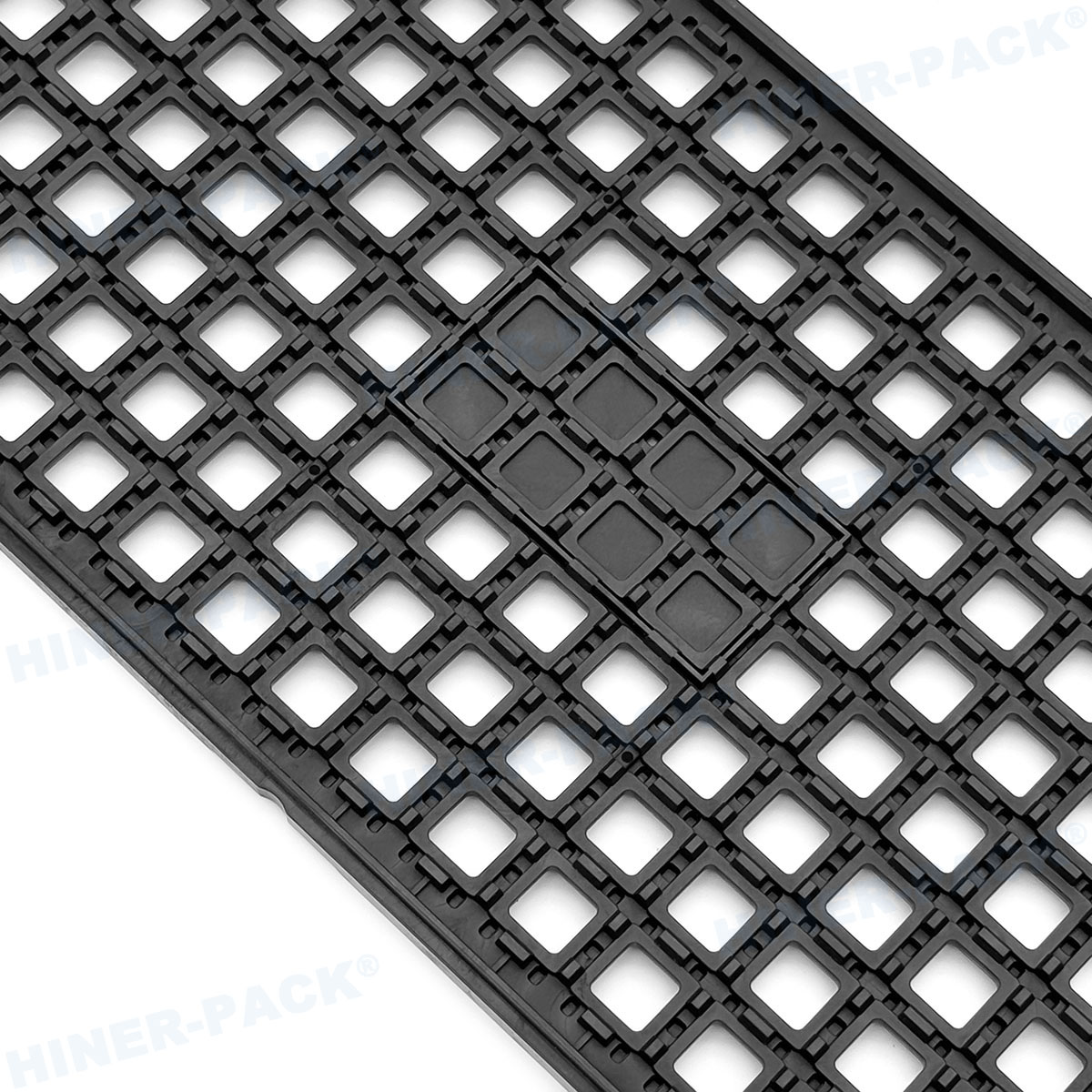
2.2 Pocket Geometry & Device Retention
Each pocket in RFIC JEDEC matrix IC trays includes chamfered
entry angles (25° to 35°) to self-center devices during high-speed placement.
For RF power amplifiers with exposed die paddles, trays incorporate sloped
sidewalls that avoid contact with bond wires or air bridges. Retention force is
measured at 0.5–1.5 N per device, preventing drop during vibration while
allowing easy vacuum-nozzle pickup.
2.3 Warpage Control After Repeated Bake Cycles
RFICs often require 125 °C baking for 24–48 hours before assembly. Poor tray
materials develop irreversible warpage >0.3 mm, causing jams in
pick-and-place feeders. High-performance JEDEC matrix trays use glass-filled PEI
(Ultem 2300 grade), maintaining flatness under 0.15 mm after 10 thermal cycles.
This directly translates to uptime in Fuji or Siemens placement lines.
3. Integration with Automated Semiconductor Workflows
Modern RFIC manufacturing uses JEDEC trays as work-in-process carriers across
die sort, tape-and-reel, and board assembly. The following compatibility aspects
determine whether a tray passes factory acceptance:
Tray stack height – Maximum 27 mm for standard magazine
loaders (e.g., Mühlbauer, Advantest).
Corner identifiers – Optical recognition features (notches,
dots) for automated tray changers.
Barcode labels – Recessed areas for 2D DataMatrix codes
without interfering with stackability.
Downtime impacts – Tray-to-tray coplanarity variations
<0.1 mm ensures no feeder retraction errors.
Equipment suppliers like YAMAHA, ASM, and Universal Instruments publish tray
compatibility lists. The RFIC
JEDEC matrix IC trays from Hiner-pack are
pre-validated for SMT lines running Infineon, Qorvo, and Skyworks RF components,
with mechanical drawings certified to JEDEC MO-350 and MO-369.
4. Industry Pain Points and Data-Driven Solutions for RFIC Tray
Selection
Based on field returns from six contract manufacturers, the top five failure
modes related to improper JEDEC tray specification for RFICs are:
Issue 1 – ESD damage to GaAs HEMT devices
Standard
carbon-loaded trays generate tribocharge >2 kV during sliding.
Solution: Specify dissipative multilayer trays with controlled
tribocharge <100 V per ANSI/ESD STM3.1. Hiner-pack provides
certified test reports for each production lot.
Issue 2 – Contamination from tray outgassing
Volatile
organic compounds (VOCs) from recycled ABS condense on RFIC bond pads,
increasing contact resistance. Solution: Use injection-molded
PPS or PEI trays that meet ionic cleanliness per IPC-9203.
Issue 3 – Pocket dimension mismatches for thin RF
filters
0.3 mm thick SAW filters shift in oversize pockets, causing
pick-up errors. Solution: Custom matrix trays with
device-specific pocket depth and sidewall draft angles.
Hiner-pack uses coordinate measurement machine (CMM) validation
for each cavity.
Issue 4 – Tray warpage during 150 °C burn-in
Standard
trays exceed 0.5 mm warpage after hot storage, jamming handlers.
Solution: Specify glass-reinforced thermoplastics with CTE
matched to FR4 (14–16 ppm/°C).
Issue 5 – Poor compatibility with JEDEC tray
stackers
Missing stack ribs or non-standard corner radius cause
tipping. Solution: Verify tray design against JEDEC Publication
95 Section 2.1 (outer corner radius R3).
5. Materials Selection Guide: ABS, PEI, PPS, and Conductive Polymers for
RFIC Trays
Selecting the right substrate for RFIC JEDEC matrix IC trays involves balancing cost, temperature range, and surface resistivity. The table
below summarizes commercially proven options used by tier‑1 RF fabs.
Modified ABS (antistatic) – Operating -40 °C to +85 °C,
surface resistivity 10⁹-10¹¹ Ω/sq. Low cost, but not bakeable above 85 °C.
Suitable for short-term in-process transport only.
Polyethersulfone (PES) / PEI – Continuous use at 170 °C,
resistivity 10⁶-10⁹ Ω/sq via internal conductive additives. Preferred for
burn-in and MSL baking. Higher cost but reusable >100 cycles.
Polyphenylene sulfide (PPS) with carbon fiber – Lowest CTE
(20 ppm/°C) and excellent chemical resistance. Resistivity 10³-10⁵ Ω/sq
(conductive). Recommended for RFIC power amplifiers because of low ionic
contamination.
Multilayer co-extruded sheets – Outer dissipative layers
(10⁸ Ω/sq) over conductive core (10³ Ω/sq). Eliminates carbon shedding.
Hiner-pack uses this for all JEDEC trays destined for
automotive radar RFICs (77 GHz).
6. Cleanroom Protocols and Packaging for RFIC JEDEC Trays
Once manufactured, RFIC JEDEC matrix IC trays must be
cleaned and packaged to ISO 14644‑1 Class 7 (Class 10,000) standards. Typical
process: ultrasonic wash with deionized water + mild surfactant, followed by
HEPA-air drying. Trays are then double-bagged in static-shielding bags with
desiccant for MSL-sensitive RFICs. Each master carton includes a certificate of
conformance listing surface resistivity, flatness, and outgassing results. For
high-volume fabs, Hiner-pack offers tray washing validation
services, including particle count per IEST-RP-CC003.4.
7. Frequently Asked Questions (FAQs)
Q1: Are RFIC JEDEC matrix IC trays compatible with automated tray
stackers from Advantest or Seiko Epson?
A1: Yes,
provided the tray meets JEDEC Registration Outline dimensions (e.g., 322 mm
length, 2.5 mm corner radius). Stacking ribs, anti-slide bumps, and corner notch
positions must match the equipment’s JEDEC configuration file.
Hiner-pack supplies trays pre-configured for Advantest M6242
handlers and Seiko Epson automatic tray exchangers.
Q2: Can JEDEC matrix trays be reused for RFICs after high-temperature
baking at 150 °C?
A2: Only trays made from
high-temperature thermoplastics like PEI (Ultem) or PPS survive repeated 150 °C
bake cycles without warpage. Standard ABS trays will deform permanently after
one cycle. Always verify the continuous use temperature rating—look for
“bakeable” on the technical datasheet.
Q3: What is the recommended cleaning method for trays that have
visible residue?
A3: Use a non-ionic detergent
(e.g., Terotex) at 50 °C, followed by DI water rinsing and drying at 60 °C for 2
hours. Avoid isopropyl alcohol on carbon-loaded trays, as it can dissolve
antistatic agents. Hiner-pack provides validated cleaning
protocols upon request.
Q4: How do I measure surface resistivity of my existing RFIC JEDEC
matrix IC trays?
A4: Per ANSI/ESD STM11.11, place a
concentric ring probe on a clean, dry tray surface, apply 10 V–100 V, and record
resistance after 15 seconds. Acceptable range: 1×10⁴ to 1×10¹¹ Ω. Values below
1×10³ Ω indicate conductive (potential short risk for RF devices).
Q5: Can you provide custom matrix tray designs for non-standard RFIC
packages (e.g., 5x5 mm LGA with side
castellations)?
A5: Yes. Most RFIC JEDEC trays are
custom-molded to pocket geometry and device array. Hiner-pack offers 3D cavity modeling, rapid tooling (3–4 weeks), and CMM first-article
inspection. Contact with your mechanical drawing and quantity forecast for a
feasibility review.
8. Conclusion and Technical Inquiry
Selecting the correct RFIC
JEDEC matrix IC trays eliminates handling defects, improves SMT
placement yield, and ensures compliance with automotive-grade IATF 16949
standards. From material physics (tribocharge, Tg, CTE) to handler interface
details (corner taper, stack pitch), every parameter influences the total cost
of RFIC assembly. Leading semiconductor contract manufacturers rely on validated
tray suppliers that publish full material declarations and provide ESD control
plans.
Request a quote or engineering consultation – Hiner-pack supplies
JEDEC matrix trays with complete documentation: surface resistivity
certificates, warpage measurement graphs, and pick-and-place test reports. For
volume production of RFIC components (Wi-Fi 7, 5G NR, automotive radar), send
your package dimensions, pocket quantity, and operating temperatures to our
engineering team for a custom tray recommendation. Click here to start
your inquiry → [https://www.waferboxes.com/contact]
© 2026 Hiner-pack – Semiconductor logistics engineered for RF
performance.