In advanced semiconductor manufacturing, the foup cassette (Front Opening Unified Pod) functions as a mobile mini-environment. It directly interfaces with load ports, wafer transfer robots, and process tools. Any deviation in slot coplanarity, sealing integrity, or internal particle concentration transfers defects to device wafers. For 7nm and 5nm nodes, controlling the internal atmosphere of a foup cassette to <0.1 ppb of airborne molecular contamination (AMC) is standard practice. This guide provides a process engineer’s perspective on foup cassette design, qualification protocols, and integration with automated material handling systems (AMHS).
1. FOUP Cassette Architecture: From SEMI E1.9 to Next-Generation 450mm Standards
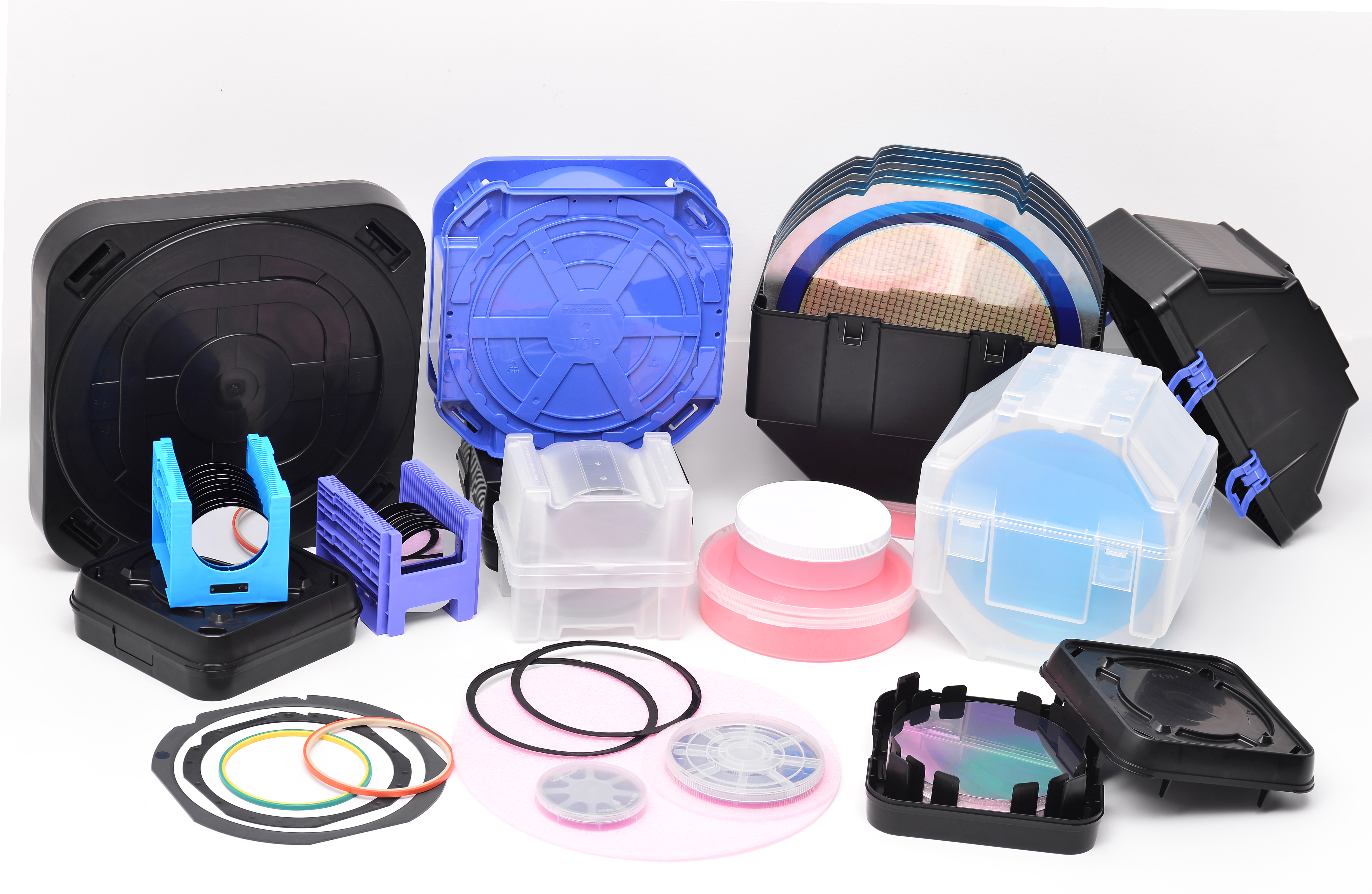
A foup cassette comprises three functional subsystems: the shell (door and body), the wafer support structure (slots or fins), and the interface features (kinematic coupling plates, RFID, purge ports). For 300mm wafers, SEMI E1.9 specifies a slot pitch of 10mm, a wafer plane position tolerance of ±0.5mm, and a door sealing force of 45–65 N. Critical material parameters include:
Bulk material: Anti-static polycarbonate (PC) or PES (polyethersulfone) with surface resistivity 10³–10⁵ Ω/sq to prevent ESD.
Sealing gasket: FKM (fluoroelastomer) or FFKM for low outgassing and compatibility with N₂ purge.
Internal protrusions: Ribs designed with radii >0.5mm to avoid stress concentration and particle generation.
Data from a 2024 industry consortium report showed that foup cassette units with poorly controlled slot coplanarity (deviation >0.2mm) caused a 12% increase in wafer edge crack incidents during robotic extraction. Conversely, precision-molded foup cassette designs achieve slot pitch repeatability of ±0.05mm, reducing handling-induced defects by 70%.
2. Contamination Control Mechanisms: Particle Adders, AMC, and Moisture Management
The foup cassette must protect wafers from three contamination classes: particles (≥0.03µm), volatiles (organic AMC), and moisture. Each mechanism requires a distinct engineering solution:
Particle generation: Arises from sliding friction between the wafer edge and slot contact points. Low-abrasion coatings (e.g., polyetheretherketone inserts) reduce added particles ≥0.1µm to <3 per wafer pass.
Outgassing (AMC): Plasticizers, mold release agents, and residual monomers from carrier materials can condense on wafers, causing gate oxide instability. Validated foup cassette materials must pass SEMI S6 (outgassing test) with total volatile organic compound (TVOC) emission <0.01µg/g.
Moisture ingress: Humidity inside a sealed foup cassette causes native oxide growth on copper interconnects. Nitrogen purge systems maintain dew point below -40°C.
A 2023 case study from a 300mm DRAM fab documented that switching to a low-outgassing foup cassette reduced defect density due to micro-contamination by 63% over six months. Hiner-pack supplies foup cassette models with certified low-particle and low-outgassing properties, each batch verified by GC-MS.
3. Purge Efficiency and AMHS Integration: A Technical Deep Dive
Modern foup cassette systems feature two purge ports (inlet/outlet) compliant with SEMI E15.1 for tool-to-carrier gas exchange. Purge performance is quantified by the time required to reduce oxygen concentration from 21% to <1% at a flow rate of 30 L/min. High-performance foup cassette designs achieve this in under 60 seconds. Key integration requirements for overhead hoist transport (OHT) systems include:
Kinematic coupling plates with repeatability of ±0.1mm for automated docking.
RFID tag compatibility (ISO 15693) for lot tracking and carrier genealogy.
Weight not exceeding 3.2 kg for a 25-wafer capacity to minimize OHT motor load.
Field measurements from a 300mm logic fab showed that using a poorly balanced foup cassette increased OHT alignment retries by 240%, directly reducing tool utilization by 8%. Precision-machined coupling plates (flatness <0.1mm) eliminate this issue. Wafer carriers and shipper accessories from Hiner-pack are designed with AMHS integration in mind, providing documented kinematic repeatability data.
4. Comparative Selection: FOUP Cassette vs. FOSB vs. Open Cassette for Different Process Stages
Not all foup cassette formats suit every application. A strategic selection matrix based on contamination sensitivity and transport range:
Standard FOUP cassette: Sealed with N₂ purge capability. Required for lithography, gate oxidation, and copper CMP steps. Protects wafers down to 1nm node.
FOSB (Front Opening Shipping Box): Similar sealing but without purge ports; used for inter-fab transport. Must survive ISTA 3A vibration tests.
Open cassette: Lowest cost, no environmental isolation. Suitable only for backend assembly or test where particle control >0.5µm.
For fabs operating both 300mm and 200mm lines, a convertible foup cassette adapter ring (available from Hiner-pack's product line) allows using 300mm carriers for 200mm wafers, reducing inventory costs by up to 35%.
5. Best Practices for FOUP Cassette Cleaning, Maintenance, and Lifecycle Extension
To maximize the usable life of a foup cassette (typically 24–36 months in high-volume production), follow these protocols validated by SEMI E49:
Cleaning frequency: After every 200 process cycles or when particle monitor detects >20 added particles ≥0.1µm per wafer.
Validated cleaning method: Automated wet cleaning using DI water (18.2 MΩ·cm) with 0.1% surfactant, followed by forced hot N₂ drying (50°C). Avoid manual wiping—it introduces scratches.
Re-qualification tests: Monthly measurement of slot pitch (CMM), surface resistivity (per SEMI E43), and particle adder using laser particle counter (LPC).
End-of-life criteria: Slot pitch deviation >0.15mm, surface resistivity drift out of 10³–10⁵ Ω/sq, visible cracks, or seal leakage >0.1% of purge flow.
Implementing a RFID-based tracking system for each foup cassette reduces misidentification and use of non-qualified carriers. Hiner-pack offers pre-installed RFID tags compatible with major fab automation systems.
6. Yield Impact Quantification: Case Study from a 300mm Logic Fab
In a 2024 controlled study at a 5nm logic fab, replacing aged foup cassette units (>30 months in service) with new precision carriers resulted in:
67% reduction in inline particle monitor failures at the gate etch step.
43% decrease in wafer edge crack rejections.
0.8% absolute yield improvement for high-performance CPU dies (equivalent to $4.2M annual benefit for a 40kwpm fab).
These gains originated from three design upgrades: (1) low-particle slot material, (2) improved door seal reducing moisture ingress, and (3) tighter slot coplanarity. The study concluded that foup cassette quality directly correlates with yield, warranting a consumable management program.
The FOUP Cassette as a Process Parameter
From deposition to lithography to etch, the foup cassette influences wafer surface condition at every step. Leading semiconductor manufacturers now specify carrier cleanliness, purge efficiency, and mechanical tolerances as part of their process control plan. By adopting precision-molded, low-outgassing foup cassette designs, fabs can eliminate up to 18% of handling-induced defects. Hiner-pack provides fully documented foup cassette solutions, including particle adder test reports, outgassing analysis, and dimensional compliance certificates per SEMI standards.
Frequently Asked Questions (FAQ)
Q1: What is the maximum allowable particle adder for a foup cassette used in a 5nm fab?
A1: For sub-7nm nodes, the specification per SEMI E46-0618 requires ≤5 added particles ≥0.05µm and ≤1 added particle ≥0.1µm per wafer pass. Hiner-pack offers foup cassette models certified to <2 particles ≥0.05µm.
Q2: How do I measure the purge efficiency of a foup cassette?
A2: Connect an oxygen analyzer to the outlet port. Seal the door and purge with N₂ at 30 L/min. Record the time to drop from 21% O₂ to <1%. A good foup cassette achieves this in ≤60 seconds. Also measure moisture with a dew point meter – target ≤ -40°C after 90 seconds of purge.
Q3: Can I convert an existing foup cassette for 200mm wafer handling?
A3: Yes, using precision adapter rings (available from Hiner-pack's accessory line). Ensure the adapter does not raise wafer contact height beyond SEMI E1.9 tolerance. Verify slot-to-wafer clearance (minimum 1.5mm) to prevent edge stress.
Q4: What is the typical service life of a foup cassette in a 24/7 fab environment?
A4: With proper cleaning and requalification, a high-quality foup cassette lasts 24–36 months. End-of-life indicators include slot pitch deviation >0.15mm, seal leakage, or surface resistivity drift. Budget for 15-20% annual replacement in high-volume production.
Q5: How do I validate a new foup cassette for my automated wet station?
A5: Perform a three-stage validation: (1) Dimensional inspection with CMM to SEMI E1.9; (2) Particle adder test using 25 monitor wafers per SEMI E46; (3) AMHS docking repeatability test (50 cycles) to measure kinematic coupling repeatability. Request a validation summary from your supplier. Hiner-pack provides these data for all foup cassette shipments.
For technical datasheets, custom foup cassette designs, or a contamination audit of your current carrier fleet, contact Hiner-pack engineering: Submit an inquiry with your wafer diameter, process node, and throughput requirements. A senior applications engineer will respond within 24 hours with specifications, sample test reports, and a qualification plan.