In semiconductor backend and front-end logistics, the efficiency of wafer handling between process steps directly impacts overall equipment effectiveness (OEE) and yield. Wafer tray stacking systems are the critical infrastructure enabling high-density storage, secure transport, and automated retrieval of wafers contained in JEDEC trays or custom substrates. As fabs scale production and embrace Industry 4.0 principles, the design, material composition, and automation readiness of these stacking systems have become pivotal. This article provides a deep technical dive into the engineering considerations, operational benefits, and selection criteria for advanced wafer tray stacking systems, incorporating insights from material handling experts at Hiner-pack.
1. The Role of Stacking Systems in Wafer-Level Packaging Logistics
Wafer tray stacking systems serve as the interface between bare wafers or diced dies and the automated material handling systems (AMHS) within a fab. These systems are not merely storage racks; they are engineered solutions designed to:
Maximize Footprint Efficiency: By utilizing vertical space, these systems reduce the cleanroom footprint required for work-in-progress (WIP) storage.
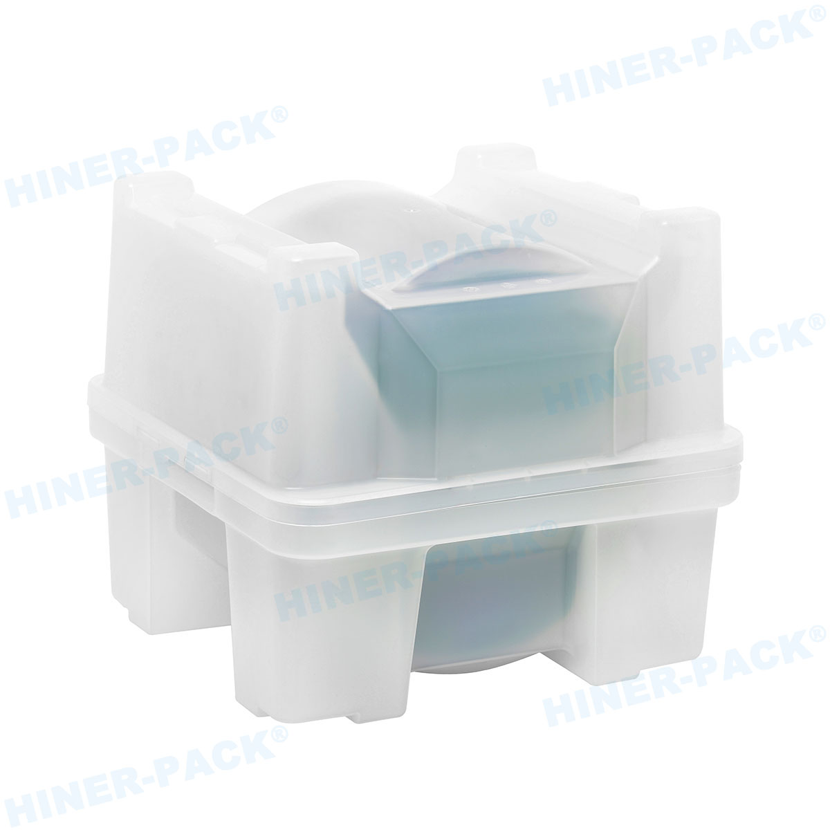
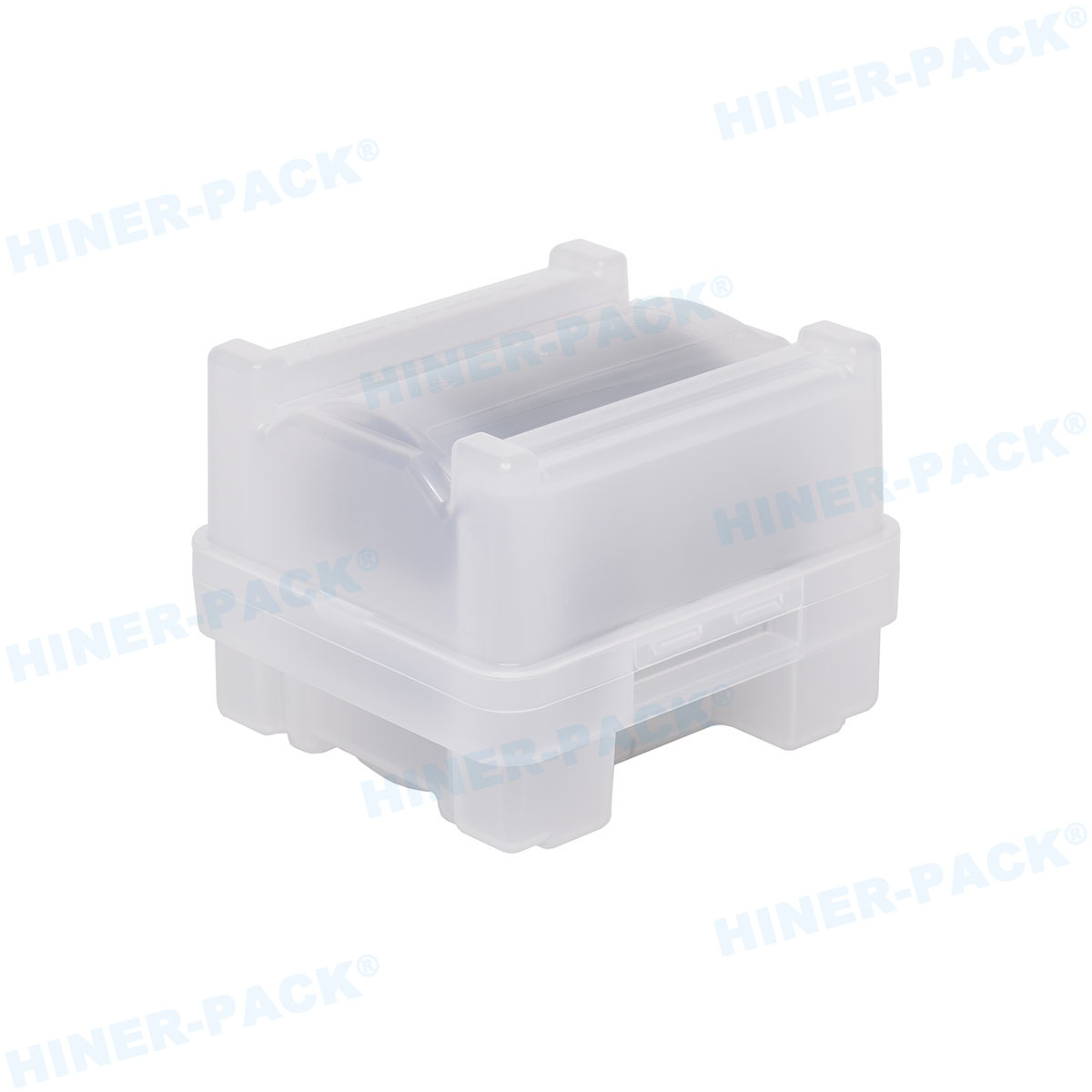
Protect Wafer Integrity: Precision-molded trays hold wafers securely, preventing edge chipping and backside damage during stacking and destacking.
Enable Automation: Standardized stacking geometries allow robotic pick-and-place tools and conveyor systems to interface without human intervention, reducing contamination risk.
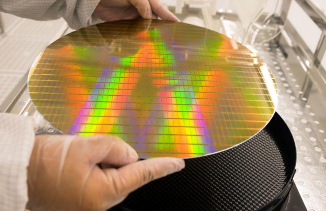
The shift towards 300mm and 450mm wafers, combined with the rise of fan-out wafer-level packaging (FOWLP), has exponentially increased the weight and sensitivity of stacked loads, demanding more robust wafer tray stacking systems.
2. Core Technical Specifications of Wafer Tray Stacking Systems
Selecting the appropriate stacking system requires a granular understanding of the physical and chemical demands of the fab environment. Key specifications include material properties, dimensional tolerances, and load capacity.
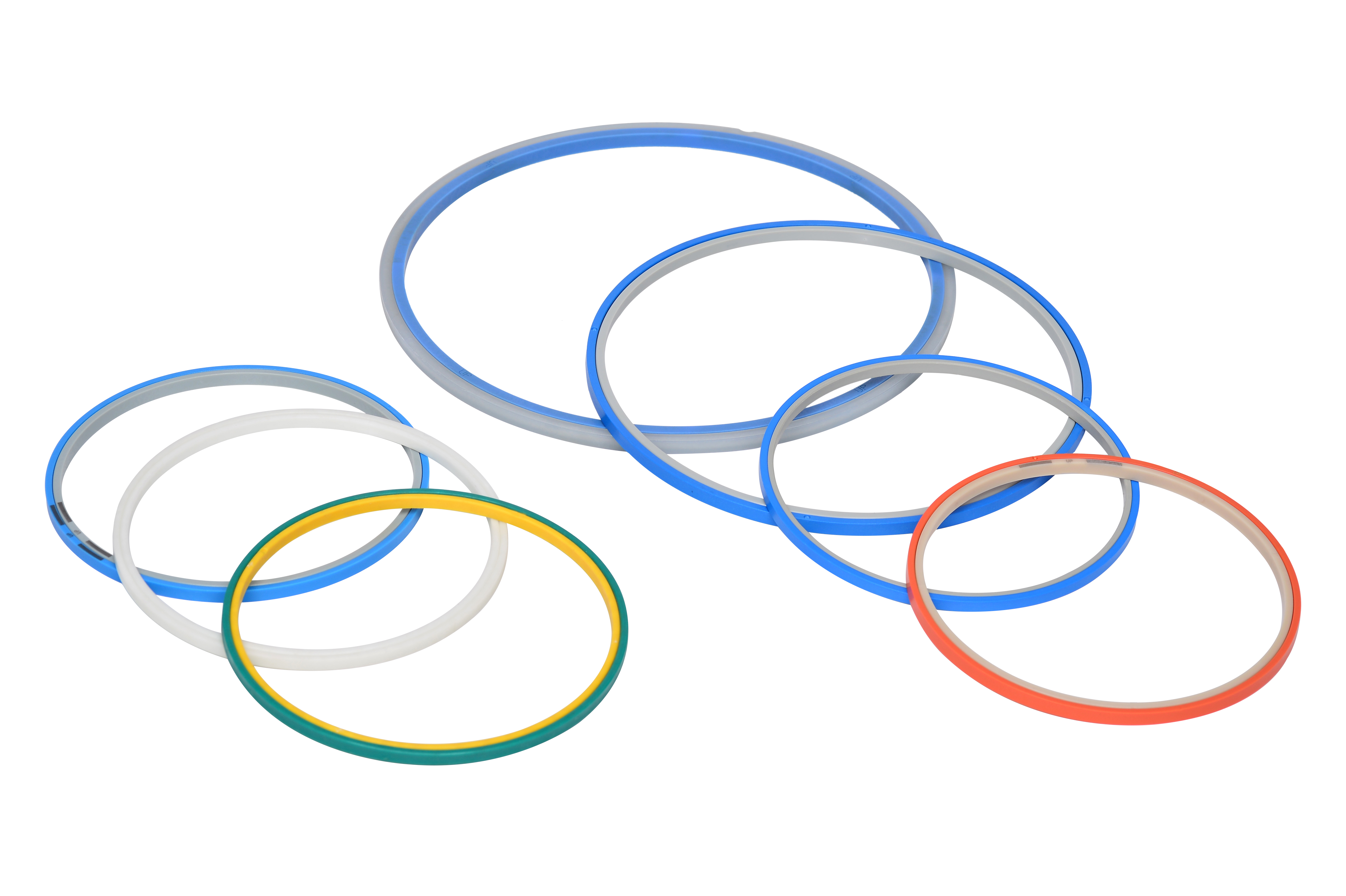
2.1 Material Selection: Beyond Basic Polymers
The materials used in trays and stack guides must meet stringent semiconductor requirements:
ESD Safety: Surface resistivity typically in the range of 10^5 to 10^11 ohms/sq to prevent electrostatic discharge. This is achieved through carbon powder or fiber compounding.
High-Temperature Resistance: For processes like die attach adhesive curing or bake steps, trays must withstand temperatures up to 150°C-200°C without warping. PEEK or high-temperature polyetherimide (PEI) are often specified.
Chemical Compatibility: Trays may be exposed to solvents or cleaning agents. Material datasheets must verify resistance to outgassing and chemical attack.
2.2 Mechanical Stability and Stack Height
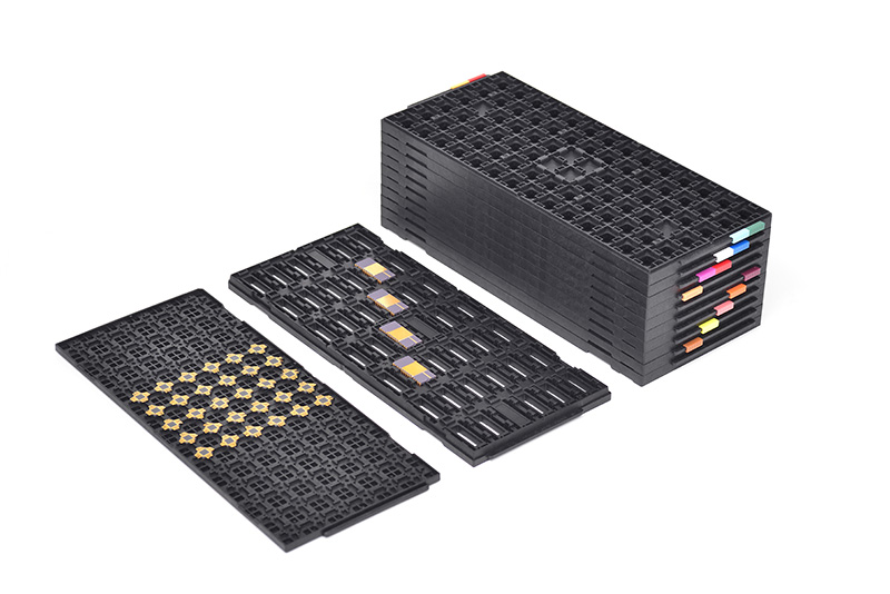
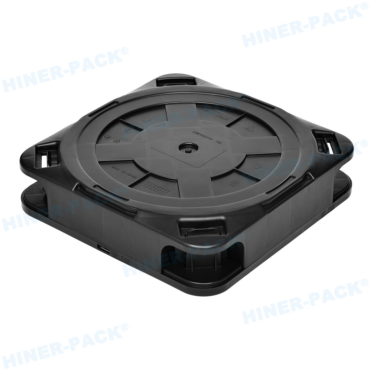
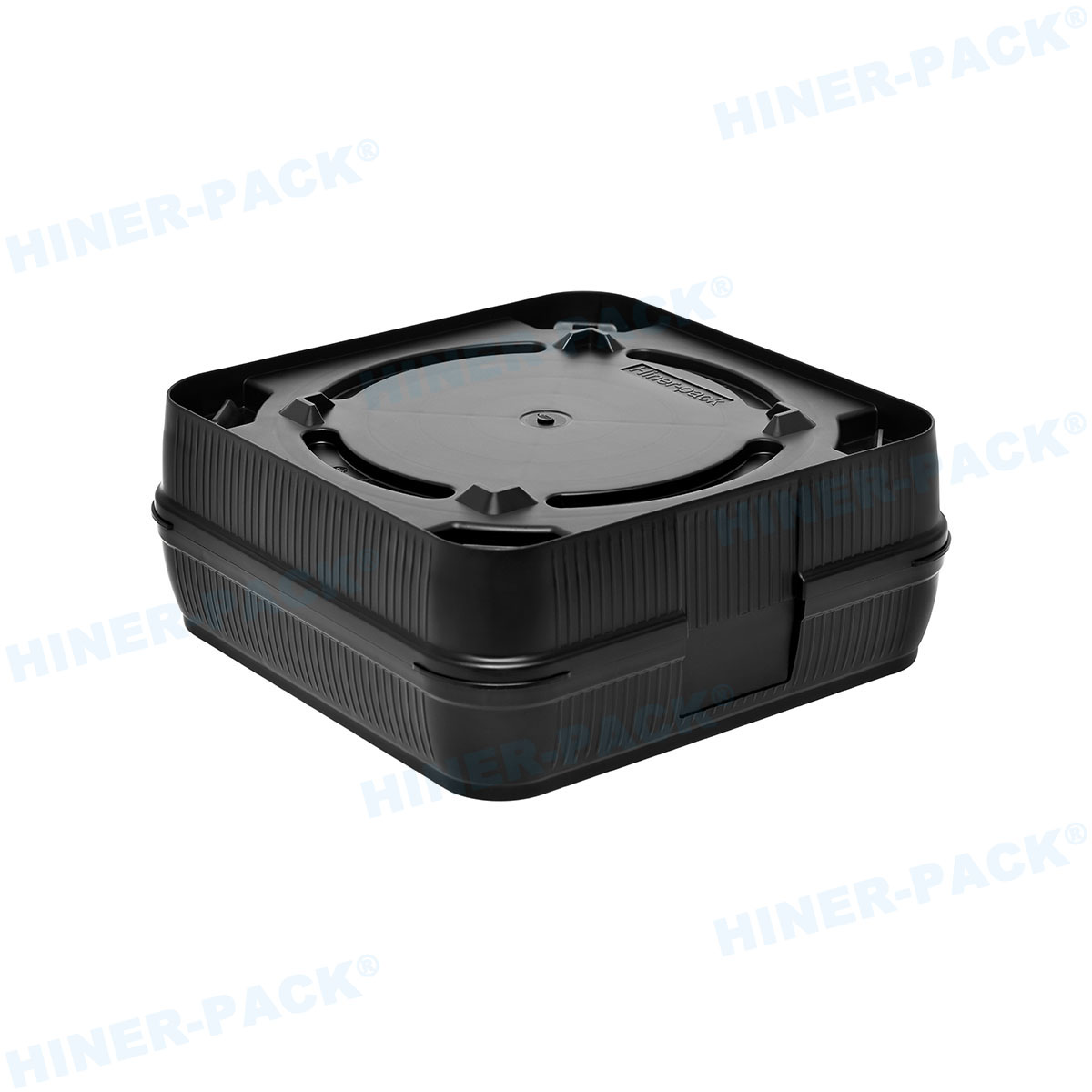
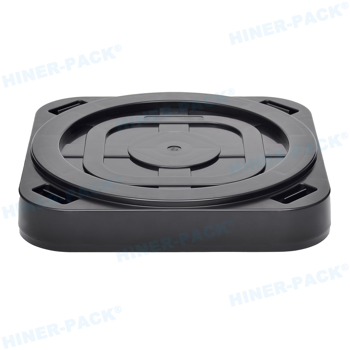
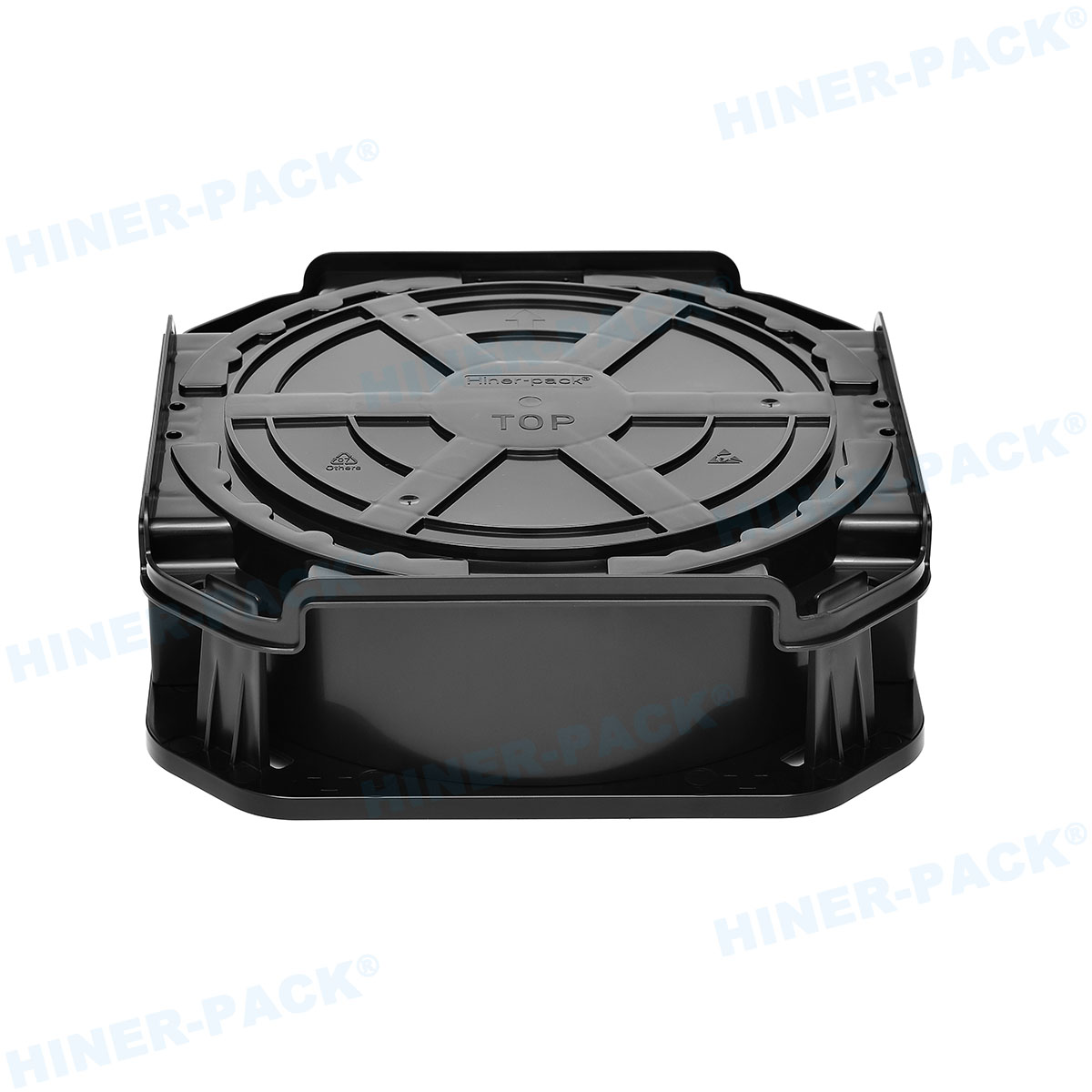
A critical parameter is the maximum stack height before the bottom trays experience compressive creep or the stack becomes unstable. Modern wafer tray stacking systems incorporate interlocking features such as alignment pins and recessed feet. These features ensure that stacks of 20, 30, or even 50 trays remain vertically aligned for robotic gripping. Finite element analysis (FEA) is increasingly used during the design phase to predict deformation under load.
3. Automation Integration: The Smart Fab Imperative
As fabs move towards lights-out manufacturing, the compatibility of stacking systems with automation equipment is non-negotiable.
3.1 Standardized Interfaces for Robotic Handling
Automated stack handling requires precise registration. Wafer tray stacking systems must feature:
Edge Grip Profiles: Chamfered edges that allow end-effectors to slide underneath trays without shaving particles.
Barcode or RFID Integration: Recessed pockets on trays for attaching machine-readable labels, enabling real-time WIP tracking.
Stack Centering Guides: Features that automatically align stacks when placed on conveyors or AGV/AMR load ports.
3.2 Case Study: Automated Destacking in Assembly Lines
In a high-volume manufacturing (HVM) backend facility, the cycle time for destacking a tray from a stack is a key performance indicator. Advanced systems, such as those designed by Hiner-pack, utilize magazine-style stackers that separate individual trays using vacuum pickups with integrated mapping sensors. This reduces the risk of "double-picking" (grabbing two trays at once) which can cause wafer breakage and tool downtime.
4. Operational Challenges and Mitigation Strategies
Even with well-designed hardware, wafer handling in trays presents several operational pain points that must be addressed through system design and protocols.
4.1 Particle Generation and Cross-Contamination
The friction between stacked trays is a primary source of particles. Solutions include:
Soft-Landing Features: Micro-ribs or raised contact points that minimize surface area contact.
Wear-Resistant Coatings: Applying permanent anti-friction coatings to tray feet and contact surfaces.
Regular Cleaning Cycles: Implementing automated tray cleaning stations that use deionized (DI) water and nitrogen blow-off.
4.2 Inventory Management of Stacked WIP
Managing thousands of stacked trays containing different wafer lots is a data challenge. Modern wafer tray stacking systems are increasingly paired with manufacturing execution systems (MES) that track each tray's cycle count and clean status. This prevents the use of degraded trays that could compromise yield.
4.3 Ergonomics and Manual Handling Interfaces
While automation is the goal, manual intervention is still required for maintenance or legacy tools. Stacking systems must be designed with ergonomic handholds and manageable stack weights. Industry guidelines suggest that a full stack should not exceed 15 kg to be safely handled by a single operator, dictating the maximum number of trays per stack based on wafer weight.
5. Evaluating the ROI of Advanced Wafer Tray Stacking Systems
Investment in premium stacking systems is justified by analyzing their impact on overall operational costs.
5.1 Quantifying Throughput Gains
Consider a backend line processing 10,000 wafers per day. If an improved stacking system reduces the destacking cycle time by just 2 seconds per wafer, the daily time savings exceed 5.5 hours, translating directly into increased tool utilization. The precision of the stacking system directly correlates to robot speed; better alignment allows robots to move faster with lower risk of collision.
5.2 Yield Improvement via Defect Reduction
A study of wafer-level packaging lines indicated that switching from generic stacking trays to engineered wafer tray stacking systems with optimized contact points reduced backside scratches by 23%. For a fab processing high-value logic wafers, this yield improvement alone can justify a complete system upgrade within months.
5.3 Lifecycle Cost Analysis
The initial purchase price of a tray is only one component. High-quality systems from reputable suppliers like Hiner-pack often have a usable life of 500+ process cycles or 2-3 years of continuous use, whereas lower-cost alternatives may warp or wear out after only 200 cycles. Factoring in replacement costs and the risk of wafer loss from a failed tray, premium systems typically offer a lower total cost of ownership (TCO).
6. Future Trends: Smart Trays and Lightweight Composites
The next generation of wafer tray stacking systems is being shaped by two powerful trends: digitalization and lightweighting.
Embedded Sensors: "Smart trays" with embedded MEMS sensors can now monitor shock, vibration, and humidity during transport, providing a digital record of the wafer's environment. This data is crucial for traceability in automotive and high-reliability applications.
Carbon-Fiber Composites: To reduce stack weight and improve thermal stability, manufacturers are experimenting with carbon-fiber-reinforced polymers. These materials offer a stiffness-to-weight ratio superior to metals and standard plastics, allowing for taller, more stable stacks without increasing the load on automation equipment.
Modular Stacking Platforms: Future systems will likely feature modular bases and adjustable guide rails, allowing a single stack system to accommodate multiple tray sizes (e.g., 2-inch to 8-inch frames) with simple reconfiguration, reducing the need for dedicated tooling for each product type.
Frequently Asked Questions (FAQ)
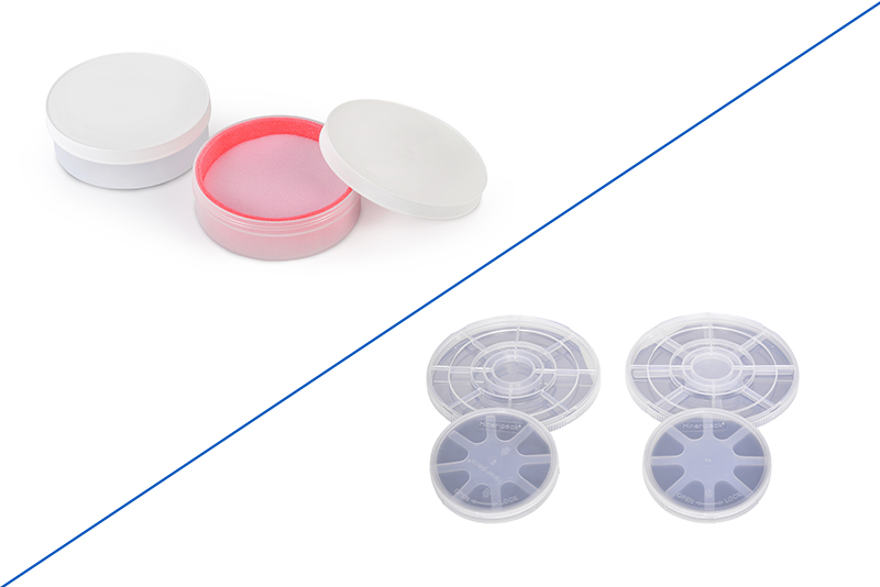
Q1: What is the difference between a wafer tray and a wafer cassette in the context of stacking systems?
A1: A wafer cassette (like a FOUP or FOSB) typically holds wafers vertically in slots and is used for lot processing. A wafer tray holds wafers horizontally, often after dicing or for single-wafer processing steps like inspection. Wafer tray stacking systems are designed specifically for stacking these horizontal trays to save space during storage and inter-process buffering.
Q2: How do I determine the maximum stack height for my wafer tray stacking system?
A2: The maximum height is determined by three factors: 1) The compressive strength of the bottom tray material (to prevent creep). 2) The stability of the stack against tipping, which is a function of tray footprint and aspect ratio. 3) The reach and lifting capacity of your automated handling equipment. Suppliers typically provide load vs. deflection charts for their systems.
Q3: Can wafer tray stacking systems be used for both bare wafers and framed wafers (tape and ring)?
A3: Yes, but the tray pockets must be specifically designed for the substrate. Bare wafers require smooth, flat pockets with edge support. Framed wafers for dicing require deeper pockets that accommodate the film frame ring without stressing the tape. Universal trays are rare; application-specific design is recommended.
Q4: What cleaning methods are recommended for wafer trays used in stacking systems?
A4: Most high-purity plastic trays can be cleaned using automated washers that employ DI water and non-ionic surfactants, followed by HEPA/ULPA-filtered hot air drying. Ultrasonic cleaning is effective but must be carefully controlled to avoid damaging embedded RFID tags or causing material degradation over many cycles. Solvent cleaning is generally avoided unless the material is chemically resistant.
Q5: How do RFID tags integrate with wafer tray stacking systems for WIP tracking?
A5: Trays are molded with a specific recess or pocket to seat an RFID inlay. The inlay is often over-molded or covered with a protective label. When stacks are moved, readers at load ports or on AGVs automatically capture the data from all trays in the stack simultaneously, linking the physical WIP to the MES database without line-of-sight scanning.
Q6: Are there SEMI standards governing wafer tray stacking systems?
A6: While specific stacking system dimensions can vary by tool manufacturer, SEMI standards like SEMI E15 (Specification for Tool Load Port) and SEMI E63 (Specification for 300mm Tray) provide guidelines for interfaces. JEDEC also publishes standards for the trays themselves (e.g., JEDEC JESD22-B112). It is crucial to ensure that your stacking system components comply with the relevant standards for your target equipment.