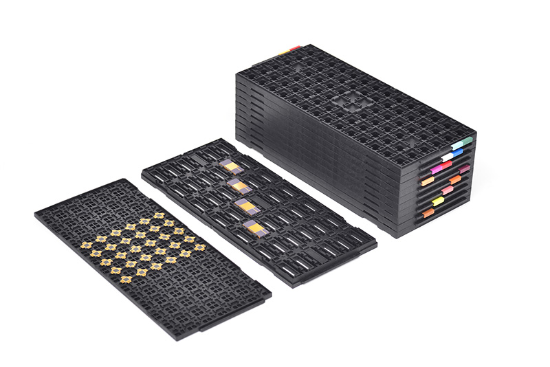
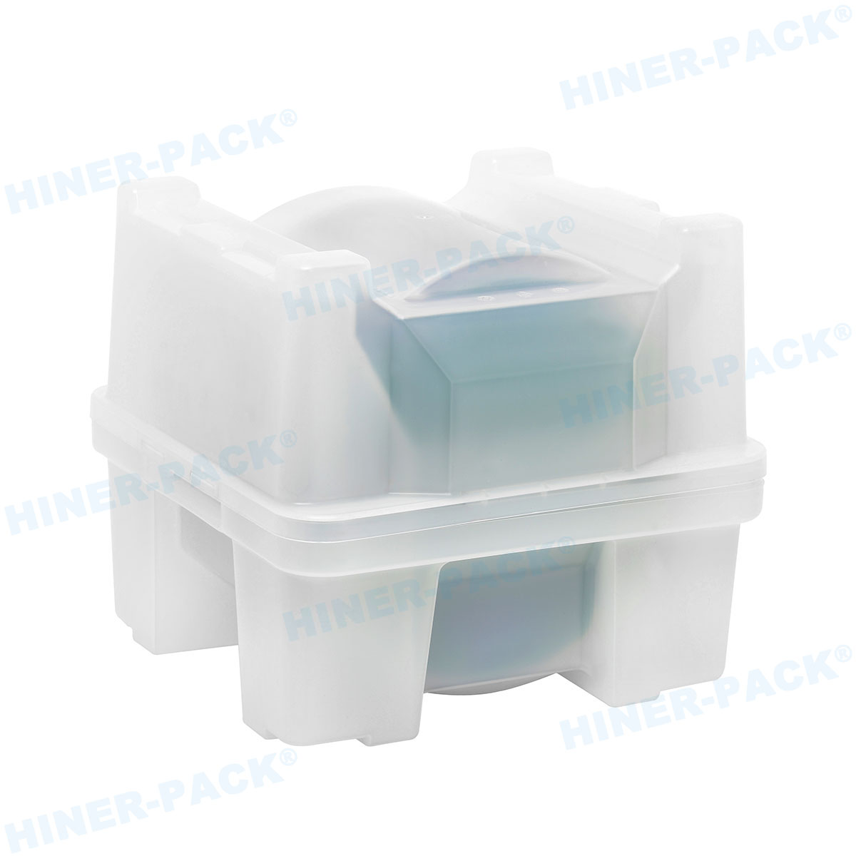
Semiconductor device manufacturing relies on precise physical containment during transport, handling, and automated assembly. Bare die, compound semiconductor components, micro-electromechanical systems (MEMS), and photonic integrated circuits require specialized chip carriers—commonly referred to as waffle packs or matrix trays—to prevent mechanical damage, electrostatic discharge, and particulate contamination. When semiconductor procurement teams evaluate a wafer tray quotation, the unit price reflects much more than simple resin weight. It encompasses mechanical tolerance engineering, material science, cleanroom processing standards, and custom tooling economics.
Understanding how individual technical parameters influence overall carrier costs allows engineering and purchasing managers to submit precise specs, eliminate unexpected charges, and ensure chip yield remains protected across global supply chains. A transparent wafer tray quotation balances stringently controlled physical properties against volume expectations and manufacturing lead times.
Material Science Selection and Surface Resistivity Standards
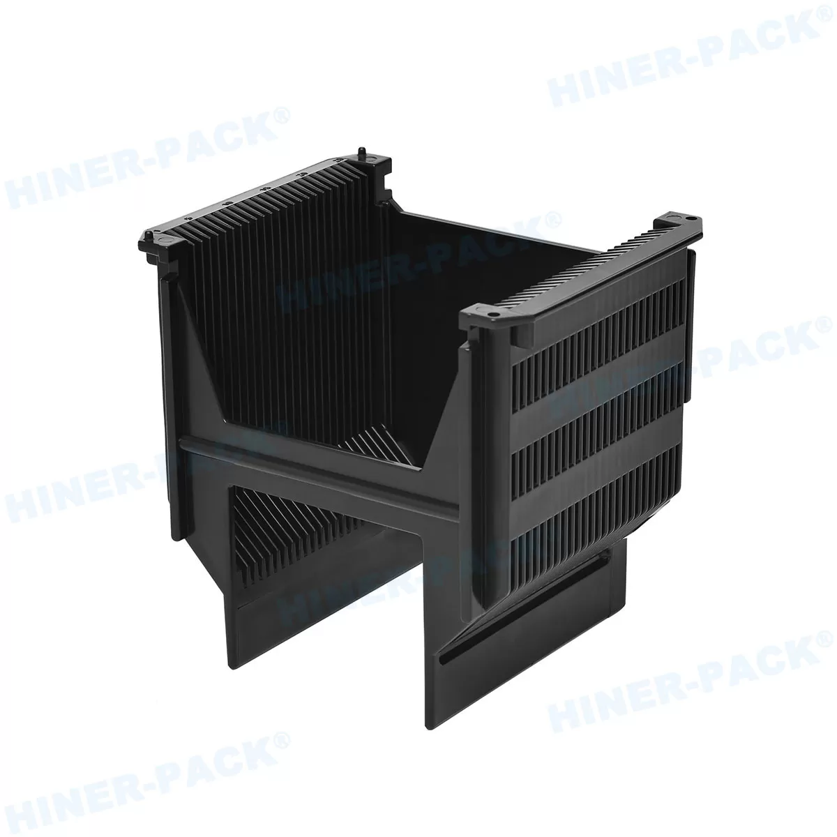
The primary material composition of a chip carrier determines its mechanical stiffness, thermal resilience, and electrostatic protection level. Semiconductor chips are vulnerable to electrostatic discharge (ESD) events, which can destroy nanoscale circuit features instantly. Consequently, carrier raw materials are engineered with specific conductive or static dissipative additives.
The core resin types utilized in carrier manufacturing include:
Polycarbonate (PC): Known for high dimensional stability, high impact resistance, and low shrinkage rates. Conductive PC is widely specified for high-precision bare die handling where pocket dimensions must maintain strict tolerances under temperature variations.
Acrylonitrile Butadiene Styrene (ABS): Offers a cost-effective solution for standard handling environments. Static dissipative or conductive ABS provides reliable structural integrity for low-to-medium thermal exposure applications.
Polypropylene (PP): Selected for applications requiring chemical resistance and flexibility. Modified PP formulations are common in standard waffle packs where economic volume production is primary.
Polyetheretherketone (PEEK) or Polyetherimide (PEI): Applied in high-temperature processing, burn-in testing, and extreme environmental conditions where standard resins deform.
To control static charges, resins are blended with conductive carbon powder, carbon fibers, or inherently conductive polymers (ICP). The target surface resistivity ranges typically fall into two categories: static dissipative ($10^6$ to $10^9 \, \Omega/\text{sq}$) or conductive ($10^3$ to $10^5 \, \Omega/\text{sq}$). Custom resin formulations that require uniform carbon fiber loading to achieve tight resistivity spreads increase raw material expenditures. Proprietary compound blends engineered by Hiner-pack utilize precisely controlled conductive fillers to guarantee static decay times under 0.01 seconds without generating microscopic carbon sloughing, directly influencing the final wafer tray quotation structure.
Pocket Geometry, Dimensional Tolerances, and Die Integrity
The design of the individual tray pocket is the main variable dictating yield protection during shipping. Micro-chipping along die edges occurs when a chip moves excessively within its pocket during vibration or impact. Conversely, if a pocket is too tight, pick-and-place automated equipment may fail to extract the die, leading to line downtime.
Engineers must define key geometric tolerances when requesting pricing for customized carriers:
Pocket Wall Draft Angles and Chamfers
Steep pocket walls maximize the number of matrix positions on a single tray but require higher precision tooling and ejector pin layouts during molding. Tapered pocket walls reduce tooling wear but increase die movement if not matched accurately with die thickness.
Corner Relief Features
Singulated chips often feature fragile edge structures resulting from saw dicing. Advanced matrix pocket designs include recessed, radiused corners. This design prevents sensitive die corners from contacting the tray wall during transit, directing physical contact entirely to the thicker, less sensitive edges of the die.
Surface Contact Area and Pedestals
For chips with delicate surface structures, such as MEMS membranes or optical sensors, pockets are engineered with raised internal pedestals or perimeter ledges. The chip rests solely on its outer inactive margin, leaving the active sensor or circuit region suspended in free air.
Tighter pocket tolerances ($\pm 0.025 \text{ mm}$ versus standard $\pm 0.05 \text{ mm}$) require high-precision CNC machining during mold fabrication and slower, highly regulated injection molding cycle times. These physical factors directly shape the manufacturing complexity and overall wafer tray quotation provided by specialized manufacturers.
Cleanroom Processing, Washing, and Contamination Control
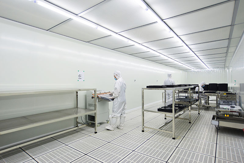
Particulate contamination on a bare die can cause short circuits, open bonds, or optical signal degradation. Standard thermoformed or injection-molded plastics inherently carry residual molding stress and surface micro-particles from production facilities. Therefore, packaging intended for cleanroom environments must undergo extensive post-molding processing.
A comprehensive wafer tray quotation reflects these post-processing procedures:
Precision Ultrasonic Washing: Trays are processed through multi-stage ultrasonic baths utilizing deionized (DI) water ($18 \, \text{M}\Omega \cdot \text{cm}$) to remove loose particulates and organic residues.
Antistatic Cleanroom Drying: Forced warm air filtered through HEPA/ULPA systems dries the components in an ISO Class 5 (Class 100) or ISO Class 4 environment to prevent airborne particle re-attachment.
Outgassing Control: For aerospace, optoelectronic, and high-vacuum applications, materials must comply with NASA outgassing standards (ASTM E595), keeping Total Mass Loss (TML) below 1.0% and Collected Volatile Condensable Material (CVCM) below 0.10%. Achieving these metrics demands high-grade, low-outgassing resins.
Cleanroom Packaging: Processed carriers are double-bagged or triple-bagged in static-shielding, vacuum-sealed moisture barrier bags (MBB) before shipment, complete with humidity indicator cards and desiccant packs.
Standard off-the-shelf industrial packaging omits these steps. When requesting pricing for semiconductor-grade carriers, specifying cleanroom washing protocols ensures that the quoted unit price matches your internal yield requirements.
Tooling Economics: Injection Molding vs. Thermoforming
Manufacturing methodology dictates non-recurring engineering (NRE) tooling charges and per-unit costs. Procurement managers must evaluate total expected volume against carrier design longevity.
Thermoforming uses heat and vacuum/pressure to shape thin extruded plastic sheets over a single-sided mold. It features low initial tooling costs and fast prototype turnarounds, making it well-suited for low-volume production or large-format handling trays where tight pocket tolerance is less strict. However, thermoformed pocket wall consistency varies across deep pockets, and material thickness distribution is inherently uneven.
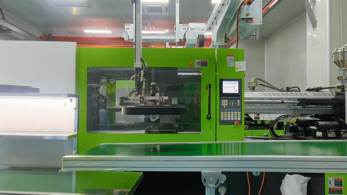
Injection molding involves injecting molten resin into a high-pressure, multi-cavity steel or aluminum mold tool. It yields exceptionally tight tolerances, high structural rigidity, repeatable pocket dimensions across multi-cavity layouts, and long tool lifespan (up to several million cycles). Non-recurring engineering (NRE) mold costs for high-density injection-molded waffle packs are higher upfront, but unit costs decrease rapidly as production scales.
Advanced production facilities at Hiner-pack maintain integrated tooling facilities that optimize mold cavity layouts, allowing customers to amortize initial NRE costs across initial production runs while maintaining precise geometric consistency across long operational lifecycles.
Key Information Required to Obtain an Accurate Estimate
Delays in receiving a completed quote usually stem from incomplete technical inputs. Providing a detailed engineering datasheet during initial contact eliminates back-and-forth communication and allows application engineers to generate an accurate breakdown quickly.
When compiling a Request for Quote (RFQ), include the following specifications:
Die Dimensions: Exact length, width, and thickness ($X \times Y \times Z$) in millimeters, including dicing tolerances.
Active Surface Constraints: Identification of bump features, wire bond zones, MEMS cavities, or optical windows that must avoid mechanical contact.
Desired Matrix Configuration: Matrix size ($2\times2 \text{ inches}$, $4\times4 \text{ inches}$, or standard JEDEC outline) and target pocket count per tray.
Material and ESD Preference: Conductive Black PC, Static Dissipative Natural/Clear, or high-temperature PEEK, including required surface resistivity ranges.
Automated Handling Compatibility: Specific automated pick-and-place machine model or feeder system interfaces.
Cleanroom Protocol Requirements: Level of cleanroom washing, particle counting limits, and specialty cleanroom packaging requirements.
Annual Usage and Batch Sizes: Prototype quantities versus annual forecasted volume to assist in determining multi-cavity mold layouts.
Providing this operational context enables manufacturers to recommend standard stock tooling options where applicable, avoiding unnecessary NRE charges.
Frequently Asked Questions
Q1: What are the primary factors that cause variation in a wafer tray
quotation?
A: Price variation is primarily driven by raw material
choice (standard ABS vs. high-performance conductive PC or PEEK), pocket design
complexity, required surface resistivity tolerances, non-recurring mold tooling
charges, and cleanroom washing/packaging specifications.
Q2: Why is conductive polycarbonate more expensive than standard
antistatic packaging plastic?
A: Conductive polycarbonate requires
uniform dispersion of high-grade carbon fiber or conductive carbon black within
a high-purity resin base. This ensures consistent surface resistivity ($10^4 -
10^6 \, \Omega/\text{sq}$) without carbon sloughing, providing long-term ESD
protection and higher thermal dimensional stability compared to topical
antistatic coatings.
Q3: How long does custom mold fabrication take for an
injection-molded waffle pack?
A: Standard custom mold fabrication
typically ranges from 3 to 6 weeks, depending on pocket geometry complexity,
mold cavity counts, and precision surface finishing requirements. Accelerated
prototyping options utilizing rapid soft tooling can shorten this phase for
early-stage engineering samples.
Q4: Can standard off-the-shelf waffle packs be used for sensitive
optoelectronic die?
A: Off-the-shelf trays often utilize flat pocket
floors that contact the full underside and active top area of the die if
inverted. Optoelectronic and MEMS devices usually require custom pedestal
pockets or perimeter-support designs to ensure active optical paths or flexible
micro-structures do not touch tray surfaces during transport.
Q5: What is the typical life expectancy of a high-precision
semiconductor matrix tray?
A: High-quality injection-molded trays
fabricated from conductive PC or engineered blends are designed for multi-year
reusable operational cycles in automated assembly systems. Provided they are
washed according to ESD-safe protocols and not exposed to temperatures exceeding
their heat deflection limits, they maintain dimensional stability and ESD
performance across hundreds of handling cycles.
Request Your Custom Carrier Assessment
Securing an accurate, cost-efficient carrier solution requires aligning physical component requirements with appropriate material selection, precision mold engineering, and contamination controls. To request a customized wafer tray quotation or consult with our engineering team regarding bare die carrier designs, contact Hiner-pack directly via email. Submit your component engineering drawings ($X/Y/Z$ dimensions, die features) and target annual volume metrics to receive a detailed technical proposal and financial estimate.
Email for Inquiry: rainbowzhu@hiner-pack.com / cathyxing@hiner-pack.com